EasyManua.ls Logo

Technoton DUT-E AF - Electrical Connection of DUT-E CAN

Technoton DUT-E AF
116 pages
Print Icon
To Next Page IconTo Next Page
To Previous Page IconTo Previous Page
Loading...
DUT-E installation / Electrical connection / Electrical connection of DUT-E CAN
DUT-E fuel level sensors. Operation manual. Version 8.1
© Technoton, 2020 37
2.7.4 Electrical connection of DUT-E CAN
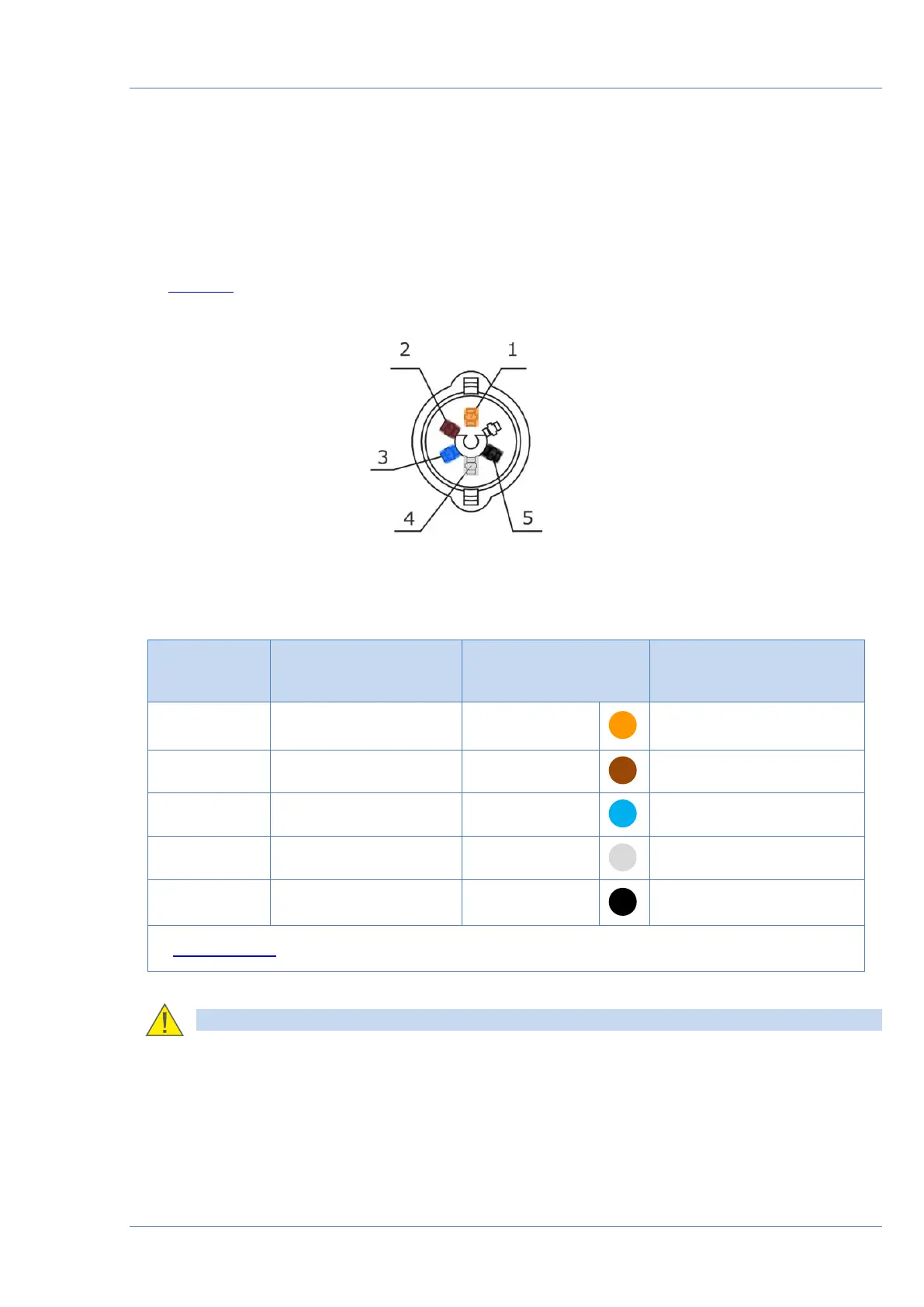
DUT-E CAN electrical connection is made according to pinout of the connector and interface
cable wires description. See figure 21 and table 7 for details.
See annex B for DUT-E CAN connection options indicating additional cables to be ordered for
particular connection type.
Figure 21 DUT-E CAN interface cable connector pinout
Table 7 DUT-E CAN interface cable wires assignment
Pin number
Wire
marking
Wire color*
Assignment
1
VBAT
Orange
Power supply “+”
2
GND
Brown
Ground “-
3
CANH
Blue
CAN-High (SAE J1939)
4
CANL
White
CAN-Low (SAE J1939)
5
KLIN
Black
K-Line (ISO 14230)
* Manufacturer reserves the right to modify wire colors
RECOMMENDATION: Primarily check wire marking when connecting DUT-E sensors.

Table of Contents