Performance
Check/Calibration-Type 453/R453
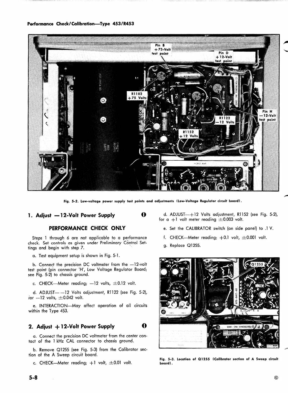
Fig.
5-2.
Low-voltage
power
supply
test points
and
adjustments
(Low-Voltage Regulator circuit
board).
1. Adiust
-12-Volt
Power Supply
0
PERFORMANCE
CHECK
ONLY
Steps 1 through 6
are
not
applicable
to a performance
check. Set controls
as
given under Preliminary C6ntrol Set-
tings
and
begin with step 7. ·
a.
Test equipment setup
is
shown
in
Fig.
5-l.
b. Connect the precision
DC
voltmeter from the
-12-volt
test point (pin connector 'H',
Low
Voltage Regulator Board;
see
Fig.
5-2)
to chassis ground.
c.
CHECK-Meter
reading;
-12
volts,
+0.12
volt.
d.
ADJUST-
-12
Volts adjustment,
R1122
(see
Fig.
5-2),
ior
-12
volts,
+0.042
volt.
e. INTERACTION-May affect
operation
of all circuits
within the Type 453.
2. Adiust + 12-Volt Power Supply
0
a.
Connect the precision
DC
voltmeter from the center con-
tact
of the 1
kHz
CAL
connector
to
chassis ground.
b. Remove
Ql
255 (see Fig.
5-3)
from the Calibrator sec-
tion of the A
Sweep
circuit
board.
c.
CHECK-Meter
reading; + 1 volt,
+0.01
volt.
5-8
d.
ADJUST-+
12
Volts adjustment,
R1152
(see
Fig.
5-2),
for a + 1 volt meter reading
+0.003
volt.
e. Set the
CALIBRATOR
switch (on side panel) to
.1
V.
f.
CHECK-Meter
reading;
+0.1
volt,
+0.001
volt.
g. Replace
Ql
255.
Fig.
5-3.
Location
of
Q
1255
(Calibrator
section
of
A
Sweep
circuit
board).
©