(A)
(8)
Fig.
5-36.
Typical
CRT
display
showing
correct one-microsecond
timing,
(8)
location
of
C530A
and
C740A
(behind
swing-.out
side
panel).
e. Set the
HORIZ
DISPLAY
switch to
DELAYED
SWEEP
(8).
f.
CHECK-CRT display for one marker each division,
-+-3%, between the
first-
and ninth-division vertical
lines
(see
Fig.
5-36A).
g.
ADJUST-C740A
(see
Fig.
5-368)
for one marker each
division.
53. Check/ Adiust High-Speed Linearity
·a.
Change the following control settings:
CH
l
VOLTS/DIV
A and 8
TIME/DIV
HORIZ
DISPLAY
20mV
.l
µs
A
0
b. Set the time-mark generator for 10-nanosecond markers.
c.
Position the display horizontally
so
the sweep starts
at
the left edge of the graticule.
d.
Set the
MAG
switch
to
X
10.
e. CHECK-CRT display for optimum linearity over the
center eight divisions of the graticule
(see
Fig.
5-37
A).
©
Performance
Check/Calibration-Type 453/R453
I
(A)
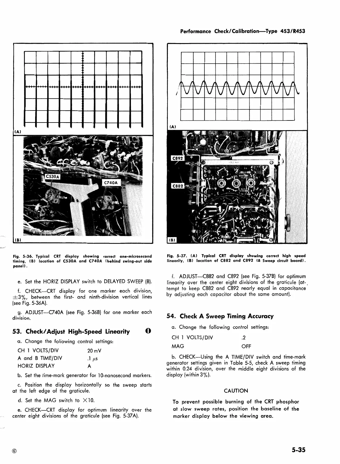
Fig.
5-37.
(A) Typical
CRT
display
showing
correct
high
speed
linearity,
(8)
location
of
C882
and
C892
(8
Sweep circuit
board).
f.
ADJUST-C882 and
C892
(see
Fig.
5-378)
for optimum
linearity over the center eight divisions of the graticule (at-.
tempt to keep
C882
and
C892
nearly equal
in
capacitance
by
adjusting each capacitor about the same amount).
54.
Check
A Sweep Timing Accuracy
a. Change the following control settings:
CH
l
VOLTS/DIV
MAG
.2
OFF
b.
CHECK-Using the A
TIME/DIV
switch
and time-mark
generator settings given
in
Table
5-5,
check A sweep timing
within 0.24 division, over the middle eight divisions
of
the
display
(within
3%).
CAUTION
To
prevent
possible burning
of
the
CRT
phosphor
at
slow
sweep
rates,
position
the
baseline
of
the
marker
display
below
the
viewing
area.
5-35
 Loading...


