Operating Instructions-Type
453
/ R453
MODE
switch to
AUTO
TRIG
and adjust the A
TIME/DIV
switch for the desired display. Since the signal source
is
trig-
gered
by
a signal that has a fixed
time
relationship
to
the
sweep, the output of the signal source can be displayed
on
the
CRT
as though the Type
453
were triggered
in
the
nor-
mal
manner
(this
method does not allow selection of trigger
level
or coupling).
Multi-Trace
Phase
Difference Measurements
Phase comparison between two signals of the same
fre-
quency can be made
using
the dual-trace feature of the
Type
453.
This
method of phase difference measurement can
be
used
up
to
the frequency
limit
of the vertical system.
To
make the comparison,
use
the following procedure.
1.
Set the Input Coupling switches
to
the same position,
depending
on
the type of coupling desired.
2.
Set the
MODE
switch to either
CHOP
or
ALT.
In
gen-
eral,
CHOP
is
more suitable for low-frequency signals and
the
ALT
position
is
more suitable for high-frequency signals.
More information on determining the mode
is
given under
Dual-Trace Operation
in
this
section.
3.
Set the
TRIGGER
switch
to
CH
1
ONLY.
4.
Connect the reference signal
to
the Channel 1
INPUT
connector and the comparison signal
to
the Channel 2
INPUT
connector.
The
reference signal should precede the com-
parison signal
in
time.
Use
coaxial cables or probes which
have equal
time
delay
to
connect the signals
to
the
INPUT
connectors.
5.
If
the signals
are
of opposite polarity,
pull
the
INVERT
switch out to invert the Channel 2 display. (Signals may be
of opposite polarity due to 180° phase difference;
if
so, take
this
into account
in
the
final
calculation.)
6.
Set the
CH
1 and
CH
2
VOLTS/DIV
switches and the
VARIABLE
VOLTS/DIV
controls so the displays are equal
and about
five
divisions
in
amplitude.
7.
Set the triggering controls
to
obtain a stable display.
8.
Set the
TIME/DIV
switch to a sweep rate which
dis-
plays about one cycle of the waveform.
9.
Move the waveforms to the center of the graticule
with
the vertical
POSITION
controls.
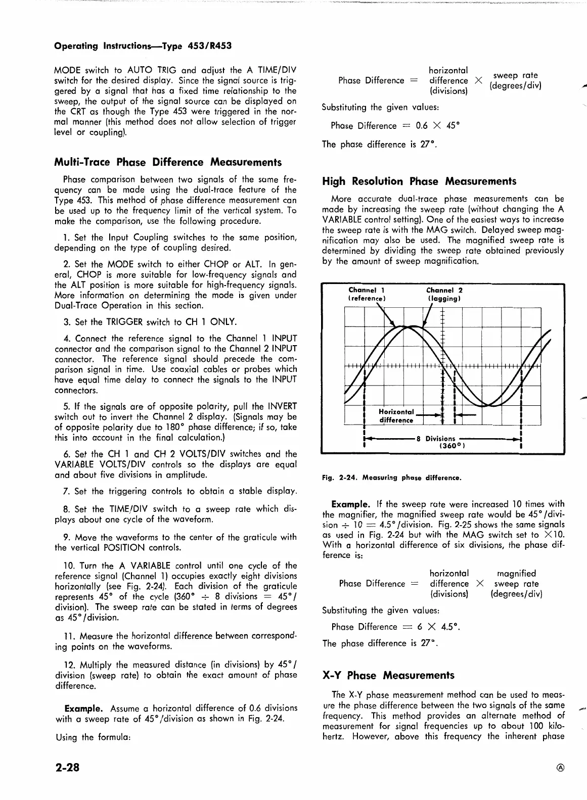
10.
Turn
the A
VARI
ABLE
control
until
one cycle of the
reference signal
(Channe·I
1)
occupies exactly eight divisions
horizontally (see
Fig.
2-24).
Each
division of the graticule
represents
45
° of the cycle
(360
° + 8 divisions =
45
° /
division).
The
sweep rate can be stated
in
terms of degrees
as
45
° I division.
11.
Measure the horizontal difference between correspond-
ing
points on the waveforms.
12.
Multiply the measured distance
(in
divisions) by 45° /
division (sweep
rate}
to
obtain the exact amount of phase
difference.
Example.
Assume
a horizontal difference of
0.6
divisions
with
a sweep rate of 45° /division as shown
in
Fig.
2-24.
Using
the formula:
2-28
horizontal
difference X sweep rate
(divisions)
(degrees/
div)
Phase Difference =
Substituting the given values:
Phase Difference = 0.6
X 45°
The
phase difference
is
27°.
High
Resolution
Phase
Measurements
More accurate dual-trace phase measurements can be
made by increasing the sweep rate (without changing the A
VARIABLE
control setting). One of the easiest ways
to
increase
the sweep rate
is
with
the
MAG
switch. Delayed sweep mag-
nification may also be used.
The
magnified sweep rate
is
determined
by
dividing the sweep rate obtained previously
by the amount of sweep magnification.
Channel
1
I reference l
Channel
2
I
lagging)
....
----8
Divisions
_____
_.
1360°1
Fig.
2-24.
Measuring
phase
difference.
Example.
If
the sweep rate were increased
10
times
with
the magnifier, the magnified sweep rate would be 45° /divi-
sion
+
10
= 4.5° /division.
Fig.
2-25
shows the same signals
as
used
in
Fig.
2-24
but with the
MAG
switch set to X
10.
With a horizontal difference of
six
divisions, the phase
dif-
ference
is:
horizontal
Phase Difference
= difference X
(divisions)
Substituting the given values:
Phase Difference
= 6 X
4.5
°.
The
phase difference
is
27°.
X-Y
Phase
Measurements
magnified
sweep rate
(degrees/
div)
The
X-Y
phase measurement method can be used
to
meas-
ure
the phase difference between the two signals of the same
frequency.
This
method provides an alternate method of
measurement for signal freque·ncies
up
to about
100
kilo-
hertz. However, above
this
frequency the inherent phase
 Loading...


