Channel
1
(reference l
Channel 2
~--Horizontal!
__
_.,.,..,.I
difference I
Fig.
2-25.
High resolution
phase-diff1~rence
measurement
with in-
creased
sweep
rate.
difference between the vertical and horizontal systems makes
accurate phase measurement difficult.
In
this
mode, one of
the sine-wave signals provides horizontal deflection
(X)
while the other signal provides
Ihe
vertical deflection
(Y).
The
phase angle between the two signals can be determined
from
the lissajous pattern as follows.
1.
Connect one of the sine·-wave signals
to
both the Chan-
nel
1
INPUT
and the Channel 2
INPUT
connectors. (Note:
steps 1 through 5 measure
inheren·r
phase difference be·tween
the X and Y amplifiers
to
prov;ide
a more accurate
X-Y
phase measurement; not necessary below about 1
kHz).
2.
Set the
HORIZ
DISPLAY
switch
to
EXT
HORIZ.
Set the
TRIGGER
switch
to
CH
1
ONLY
cJnd
the B
SOURCE
switch
to
INT.
..
.J
..........
~
t.-·".'
V'""
....
v
i..;..."'"
[.......-"
v
...
IAI
IOI
181
Operating Instructions-Type
453/R453
A
8
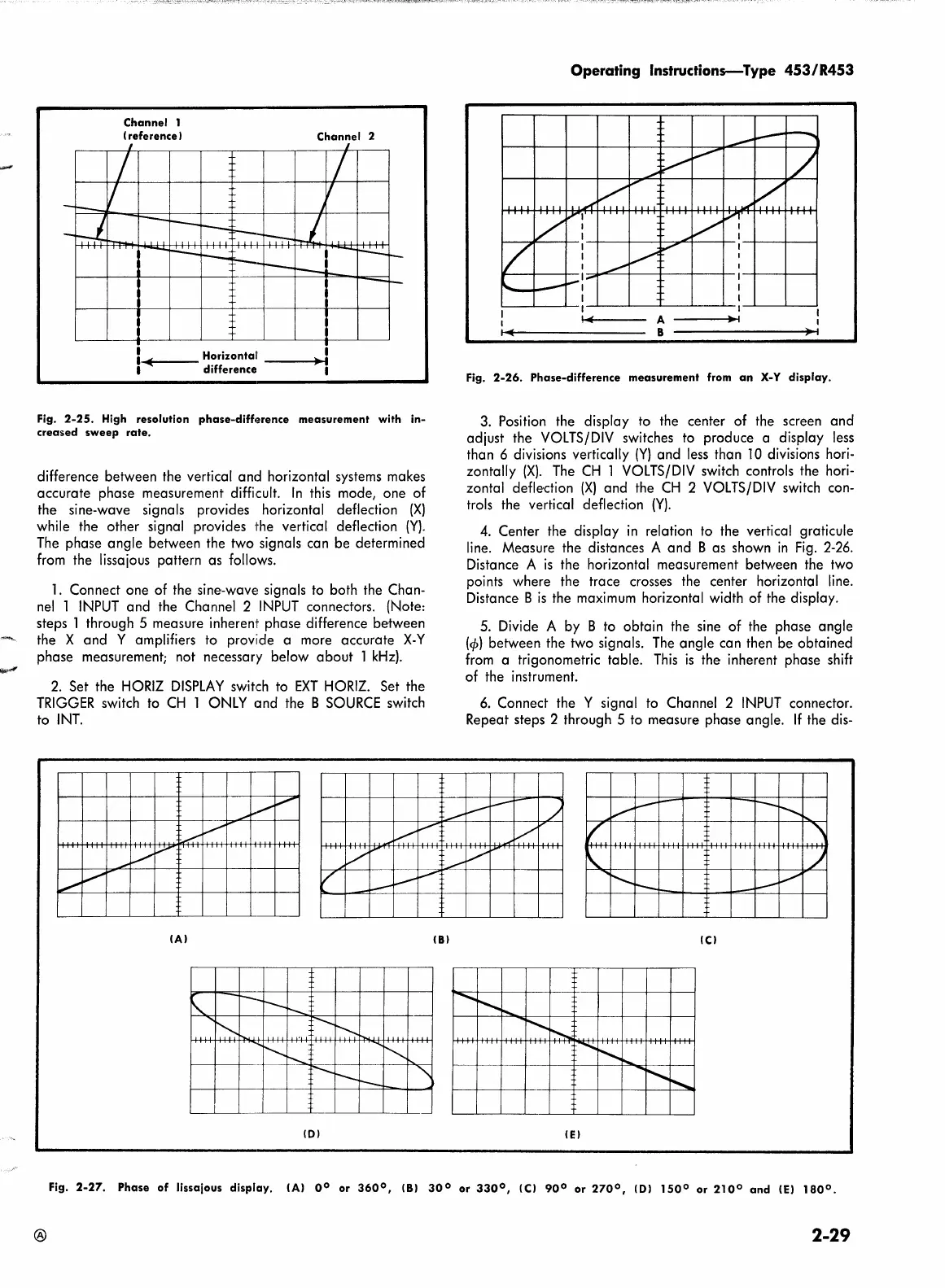
Fig.
2-26.
Phase-difference
measurement
from
an
X-Y
display.
3.
Position the display
to
the center of the screen and
adjust the
VOLTS/DIV
switches
to
produce a display
less
than 6 divisions vertically
(Y)
and
less
than
10
divisions hori-
zontally
(X).
The
CH
1
VOLTS/DIV
switch controls the hori-
zontal defledion
(X)
and the
CH
2
VOLTS/DIV
switch
con-
trols the vertical deflection
(Y).
4.
Center the display
in
relation
to
the vertical graticule
line.
Measure the distances A and B as shown
in
Fig.
2-26.
Distance A
is
the horizontal measurement between the two
points where the trace crosses the center horizontal
line.
Distance B
is
the
maximum
horizontal width of the display.
5.
Divide A by B
to
obtain the sine of the phase angle
(cp)
between the two signals.
The
angle can then be obtained
from
a trigonometric table.
This
is
the inherent phase shift
of
the instrument.
6.
Connect the Y signal
to
Channel 2
INPUT
connector.
Repeat steps 2 through 5
to
measure phase angle.
If
the
dis-
!Cl
.........
,
....
r---..
~
...........
'""'--
....
,
r--......
IEI
Fig.
2-27.
Phase
of
lissajous
display.
IAI o
0
or
360°,
181
30°
or
330°,
!Cl
90°
or
270°,
IOI
1500
or
2100
and
(El
1800.
®
2-29
 Loading...


