Circuit
Description-Type
453/R453
Channel 1 Diode
Gate
D201
Signal in from
*
D202
Channel
1 Vertical
r---------------"'
Preamp
~
Signal in from
Channel
2 Vertical
Preamp
~
R217
1--,\,
0215
-12
v \ SW230A
'--
---1
MODE
•
r-
1
I
I
I
D203 D204
R227
I
,
____
_/
-12
v
2 Diode
Gate
Signal
path
...
Reverse-biased
diode
--{:>I--
\
To
Delay-Line
Driver
~
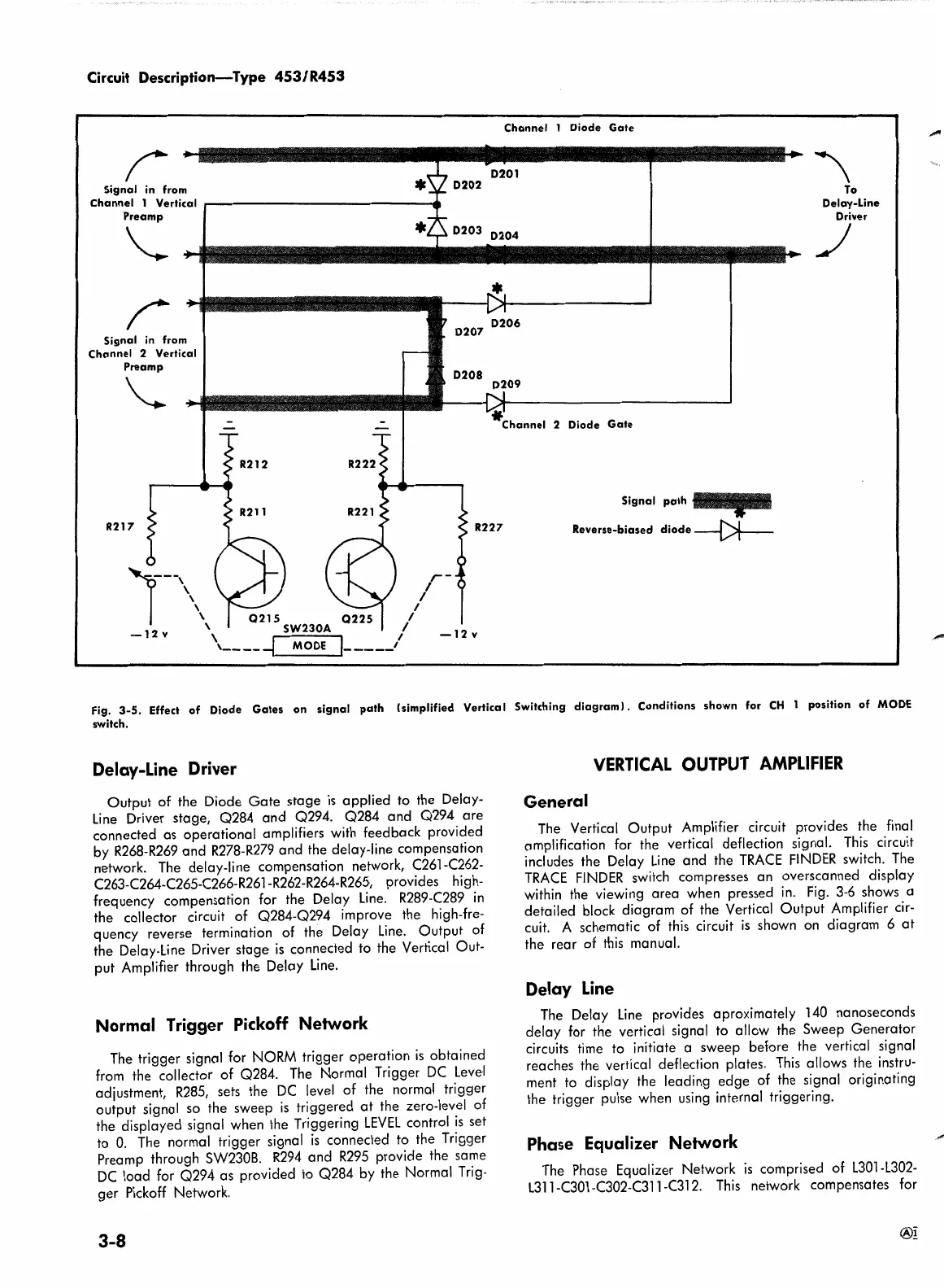
Fig.
3-5.
Effect
of
Diode
Gates
on
signal
path
(simplified Vertical Switching
diagram).
Conditions
shown
for
CH
1 position
of
MODE
switch.
Delay-Line Driver
Output of the Diode
Gate
stage
is
applied to the Delay-
Line
Driver stage, Q284 and Q294. Q284 and Q294
are
connected as operational amplifiers with feedback provided
by
R268-R269
and
R278-R279
and the delay-line compensation
network.
The
delay-line compensation network, C261-C262-
C263-C264-C265-C266-R261-R262-R264-R265, provides high-
frequency compensation for the Delay
Line.
R289-C289
in
the collector circuit of Q284-Q294 improve the high-fre-
quency reverse termination of the Delay
Line.
Output of
the Delay-Line Driver stage
is
connected to the Vertical Out-
put Amplifier through the Delay
Line.
Normal Trigger Pickoff Network
The
trigger signal for
NORM
trigger operation
is
obtained
from
the collector of Q284.
The
Normal Trigger
DC
Level
adjustment,
R285,
sets the
DC
level
of the normal trigger
output signal so the sweep
is
triggered
at
the zero-level of
the displayed signal when the Triggering
LEVEL
control
is
set
to
0.
The
normal trigger signal
is
connected to the Trigger
Preamp through
SW230B.
R294
and
R295
provide the same
DC
load for Q294 as provided to Q284 by the Normal
Trig-
ger
Pickoff
Network.
3-8
VERTICAL
OUTPUT
AMPLIFIER
General
The
Vertical Output Amplifier circuit provides the final
amplification for the vertical deflection signal.
This
circuit
includes the Delay
Line
and the
TRACE
FINDER
switch.
The
TRACE
FINDER
switch compresses an overscanned display
within the viewing area when pressed
in.
Fig.
3-6
shows a
detailed block diagram of the Vertical Output Amplifier
cir-
cuit. A schematic of
this
circuit
is
shown
on
diagram 6
at
the rear of
this
manual.
Delay Line
The
Delay
Line
provides aproximately 140 nanoseconds
delay for the vertical signal to allow the Sweep Generator
circuits time to initiate a sweep before the vertical signal
reaches the vertical deflection plates.
This
allows the instru-
ment to display the leading edge
of the signal originating
the trigger pulse when
using
internal triggering.
Phase
Equalizer Network
The
Phase Equalizer Network
is
comprised of
L30l-L302-
L31
l-C301-C302-C31 l-C312.
This
network compensates for
®!
 Loading...


