Performance
Check/Calibration-Type
453/R453
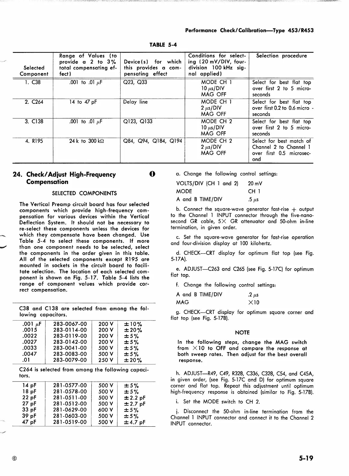
TABLE
5-4
Range
of
Values
(to
Conditions
for
select-
Selection
procedure
provide
a
2
to
3%
Device(s)
for
which ing (
20
mV
/DIV, four-
Selected
total
compensating
ef-
this
provides
a
com- division
100
kHz sig-
Component
feet)
pen
sating
effect
nal
applied)
l.
C38
.001
to
.Ol
µF
Q23, Q33
MODE
CH
l
Select for best flat
top
lO
µs/DIV
over first 2 to 5 micro-
MAG OFF
seconds
2.
C264
14
to
47
pF
Delay line MODE
CH
l Select for best flat top
2 µs/DIV
over first 0.2 to 0.6 micro -
MAG OFF
seconds
3.
Cl38
.001
to
.01
µF
Ql23,
Ql33
MODE
CH
2
Select for best flat top
lO
µs/DIV
over first 2 to 5 micro-
MAG
OFF
seconds
4.
Rl95 24 k to 300
kn
Q84, Q94,
Ql
84,
Ql
94
MODE
CH
2
Select for best match of
24. Check/ Adiust High-Frequency
Compensation
@
SELECTED
COMPONENTS
The
Vertical
Preamp
circuit
board
has
four
selected
components
which
provide
high-frequency
com-
pensation
for
various
devices within
the
Vertical
Deflection System.
It
should
not
be
necessary
to
re-select
these
components
unless
the
devices for
which
they
compensate
have
been
changed.
Use
Table
5-4
to
select
these
components.
If
more
than
one
component
needs
to
be
selected,
select
the
components
in
the
order
given
in
this
table.
All
of
the
selected
components
except
Rl
95
are
mounted
in sockets
in
the
circuit
board
to
facili-
tate
selection.
The
location
of
each
selected
com-
ponent
is
shown
on
Fig.
5-17.
Table
5-4
lists
the
range
of
component
values
which
provide
cor-
rect
compensation.
C38
and
C
138
are
selected
from
among
the
fol-
lowing
capacitors.
. 001
µ,F
283-0067-00
200
v
±10%
.0015
283-0114-00
200
v
±20%
.0022
283-0119-00
200V
±5%
.0027
283-0142-00
200
v
±5%
.0033
283-0041-00
500
v
±5%
.0047
283-0083-00
500
v
±5%
.01
283-0079-00
250
v
±20%
C264
is
selected
from
among
the
following
capaci-
tors.
14
pf
281-0577-00
500
v
I
±5%
18
pf
281-0578-00
500
v
±5%
22
pf
281-0511-00
500
v
±2.2
pf
27
pf
281-0512-00
500
v ±
2.7
pf
33
pf
281-0629-00
600
v
±5%
39
pf
281-0603-00
500
v
±5%
47
pf
281-0519-00
500
v
±4.7
pf
0
2 µs/DIV
Channel 2 to Channel l
MAG OFF over first 0.5
ond
a.
Change the following control settings:
VOLTS/DIV
(CH
l
and
2)
MODE
20mV
CH
l
A
and
8
TIME/DIV
.5
µs
microsec-
b. Connect the square-wave generator fast-rise.
+ output
to the Channel l
INPUT
connector through the five-nano-
second
GR
cable,
5X
GR
attenuator
and
50-ohm in-line
termination,
in
given order.
c.
Set the square-wave generator for fast-rise operation
and
four-division display
at
l 00 kilohertz.
d. CHECK-CRT display for optimum flat top (see
Fig.
5-17A).
e. ADJUST-C263
and
C265 (see
Fig.
5-17C) for optimum
flat top.
f.
Change the following control settings:
A
and
8
TIME/DIV
.2
µs
MAG
XlO
g. CHECK-CRT display for optimum square corner
and
flat top (see
Fig.
5-178) .
NOTE
In
the
following
steps,
change
the
MAG switch
from X
10
to
OFF
and
compare
the
response
at
both
sweep
rates.
Then
adjust
for
the
best
overall
response.
h.
ADJUST-R49, C49,
R328,
C336, C328, C54, and C45A,
in
given order, (see
Fig.
5-17C
and
D)
for optimum square
corner
and
flat top. Repeat this adjustment
until
optimum
high-frequency response
is
obtained (similar to
Fig.
5-178).
i.
Set the MODE switch to
CH
2.
j.
Disconnect the 50-ohm in-line termination from the
Channel 1
INPUT
connector and connect
it
to the Channel 2
INPUT
connector.
5-19
 Loading...


