...
,
'--------A
sweep
time
-----""'.""----fl~
I
I
~Delay
time ~I
I . I A
sweep
I
(Variable
from
~starts
B
sweep
I 1
µs
to
SO
s I
I
by
A TIME/DIV I
1
and
DELAY-TIME
I
I
MULTIPLIER)
I
I I
._.,.
__
B
sweep
time
I I
A
trigger
pulse
I
'
I
I
I
I
I
I
I
I
-
I I
11
111
I I 0
I
I
I
I
Intensified portion
of
waveform
-
-
-
-
'
'·-
-
...
...
...
-
-
I A I 8
ST
ARTS
AFTER
DELAY
TIME
1
I I
11
B
',
' \
',
'
'·
·,
\
--;-;-:-:-
~
' '
.-
I
Ir'
sweep
display
Operating
Instructions-Type
453/R453
....
1
----------A
sweep
time---------.
I
I
~Delay
time~,~--
A
sweep
I
(Variable
from
"arms"
8
sweep
I 1 µs to
SO
s
I
by
A TIME/DIV
:
and
DELAY-TIME
I
MULTIPLIER)
I
I
A
trigger
pulse
I
8
sweep
waits
----for
next
trigger
;----8
trigger pulse
-4-=---
8
sweep
time
A
sweep
display
i
!
,-
I
1
_,.
~
''
I
I
I
I
I
I
I
~
i
I
l
--
''''
''
''
Intensified portion
of
waveform
-
-
-
''
I
1111
I I I I
-
181
TRIGGERABLE
AFTER
DELAY
TIME
'
\
I I
11
'
'
\
.
I
11
o
~,
\.
',
·~
'
.,
'
11
I
Ill~
''
..
8
sweep
display
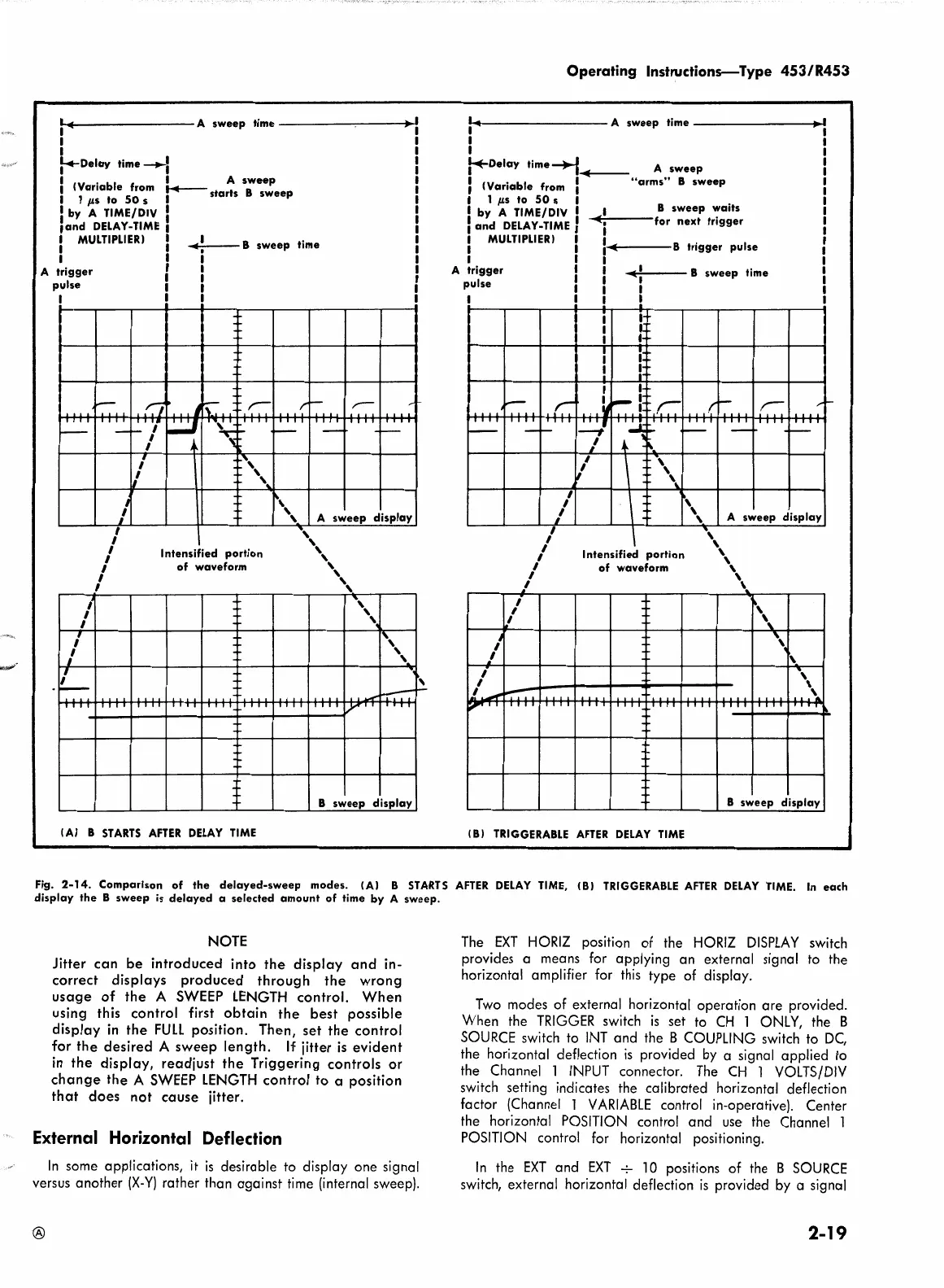
Fig.
2-14.
Comparison
of
the
delayed-sweep
modes. IAI 8
STARTS
AFTER
DELAY
TIME,
181
TRIGGERABLE
AFTER
DELAY
TIME.
In
each
display
the
8
sweep
is
delayed
a selected
amount
of
time
by
A
sweep.
NOTE
Jitter
can
be
introduced into
the
display
and
in-
correct displays
produced
through
the
wrong
usage
of
the
A
SWEEP
LENGTH
control.
When
using this control first
obtain
the
best
possible
display
in
the
FULL
position. Then,
set
the
control
for
the
desired A
sweep
length.
If
jitter
is
evident
in
the
display, readjust
the
Triggering controls or
change
the
A
SWEEP
LENGTH
control to a position
that
does
not
cause
jitter.
External Horizontal Deflection
In
some applications,
it
is
desirable to display one signal
versus another
(X-Y)
rather than against
time
(internal sweep).
The
EXT
HORIZ
position of the
HORIZ
DISPLAY
switch
provides a means for applying an external signal to the
horizontal amplifier for
this
type of display.
Two
modes of external horizontal operation are provided.
When the
TRIGGER
switch
is
set to
CH
l
ONLY,
the B
SOURCE
switch to
INT
and the B
COUPLING
switch to
DC,
the horizontal deflection
is
provided
by
a signal applied to
the Channel l
INPUT
connector.
The
CH
l
VOLTS/DIV
switch setting indicates the calibrated horizontal deflection
factor (Channel l
VARIABLE
control in-operative). Center
the horizontal
POSITION
control and
use
the Channel l
POSITION
control for horizontal positioning.
In
the
EXT
and
EXT
-7-
l 0 positions of the B
SOURCE
switch, external horizontal deflection
is
provided
by
a signal
2-19