Performance
Check/Calibration-Type
453/R453
TABLE
5-7
Delayed
Sweep
Accuracy
A TIME/DIV
B TIME/DIV
Time-Mark
Allowable
error for
Switch Setting
Switch Setting
Generator
Output
given
accuracy
l µs .l
µs
l microsecond
2
µs
.l
µs
l microsecond
5
µs
.5
µs
5 microsecond
10
µs
l
µs
l 0 microsecond
20
µs
l
µs
l 0 microsecond
50
µs
5
µs
50
microsecond
.l
ms
10
µs
0.1
millisecond
.2
ms
10
µs
0.1
millisecond
±
12
minor dial divisions
.5
ms
50
µs
0.5
millisecond
(+
l.5% over center eight
l
ms
.l
ms
1 millisecond
divisions)
2
ms
.l
ms
l millisecond
5
ms
.5
ms
5 millisecond
10
ms
l
ms
l 0 millisecond
20
ms
l
ms
l 0 millisecond
50
ms
5
ms
50
millisecond
. l s
10
ms
0.1
second
.2
s
10
ms
0.1
second
.5s
50
ms
0.5
second
+20
minor dial divisions
l s
. l s
l second
(+2.5%
over center eight
2s
. l s
l second
divisions)
5s
.5
s
5 second
e. Repeat check
at
each major dial division between
9.00 and l.00.
6
·~.
Check/ Adiust External Horizontal Gain 0
·""""
a. Connect the standard amplitude calibrator to the Chan-
60.
Check Delay-Time Jitter
a. Change the following control settings:
DELAY-TIME
MULTIPLIER
l.00
B
TIME/DIV
l
µs
b.
Position the pulse near the center of the display area
with
the
DELAY-TIME
MULTIPLIER
dial.
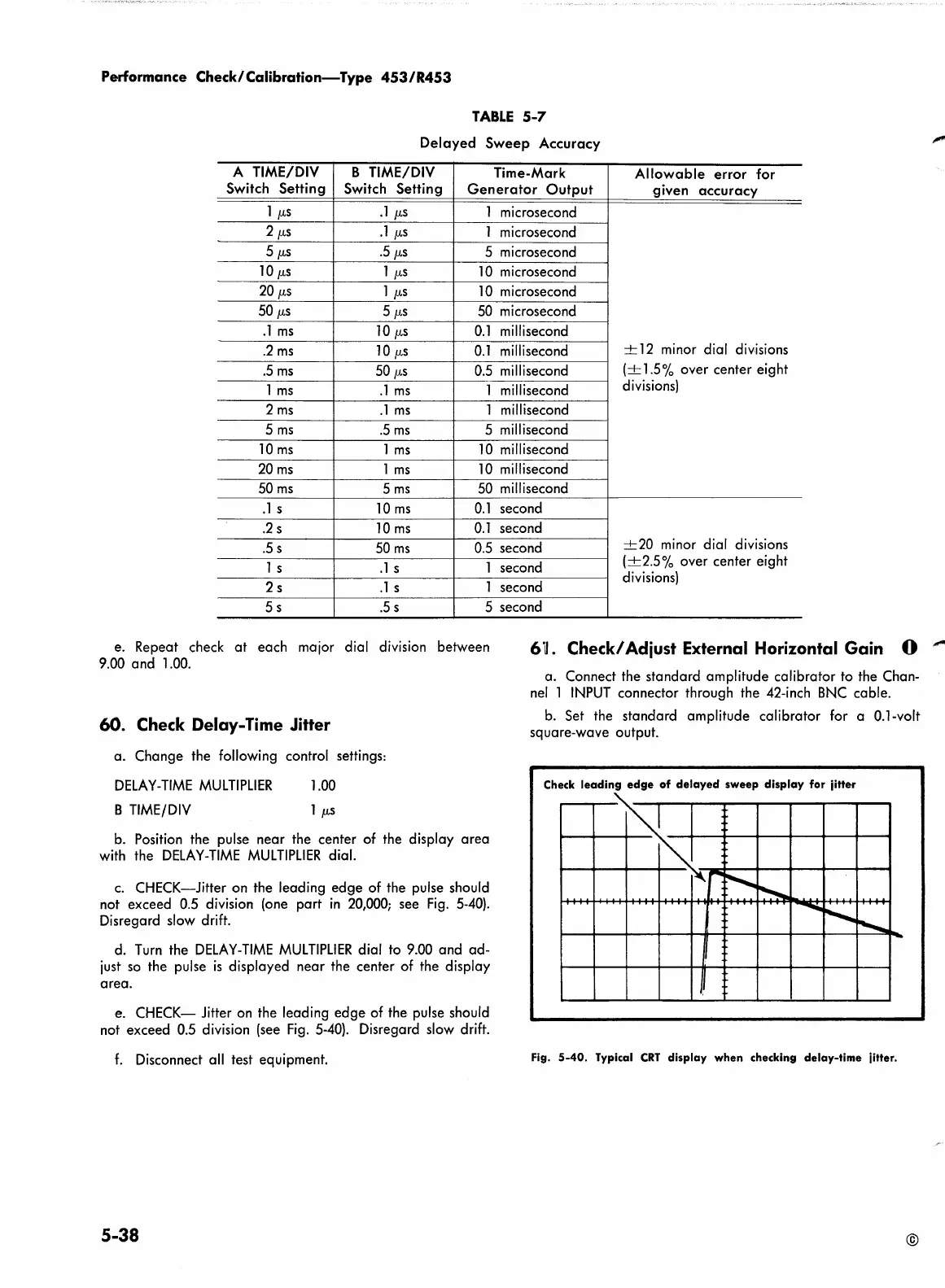
c.
CHECK-Jitter on the leading edge of the pulse should
not exceed 0.5 division (one part
in
20,000;
see
Fig.
5-40).
Disregard slow drift.
d.
Turn
the
DELAY-TIME
MULTIPLIER
dial to 9.00 and ad-
just
so
the pulse
is
displayed near the center of the display
area.
e. CHECK- Jitter on the leading edge of the pulse should
not exceed 0.5 division (see
Fig.
5-40).
Disregard slow drift.
f.
Disconnect all test equipment.
5-38
nel
l
INPUT
connector through the 42-inch
BNC
cable.
b.
Set the standard amplitude calibrator for a 0.1-volt
square-wave output.
Check
leading
edge
of
delayed
sweep
display
for jitter
m
lo
r
~
~
. .
-.........
............
...........
-
J,
Fig.
5-40.
Typical
CRT
display
when
checking
delay-time
jitter.
©
 Loading...


