Maintenance-Type
453/R453
Collector
Flat
side
Emitter
ColledO<
I a
...
\
Flat
side
Source
Source
Metal-Case
Transistors
Plastic-Case
Transistors
Dual Field-
Effect
Transistor
Collector
Gate
Source
Emitter
Dual
Transistors
Power
Transistors
Field-Effect
Transistor
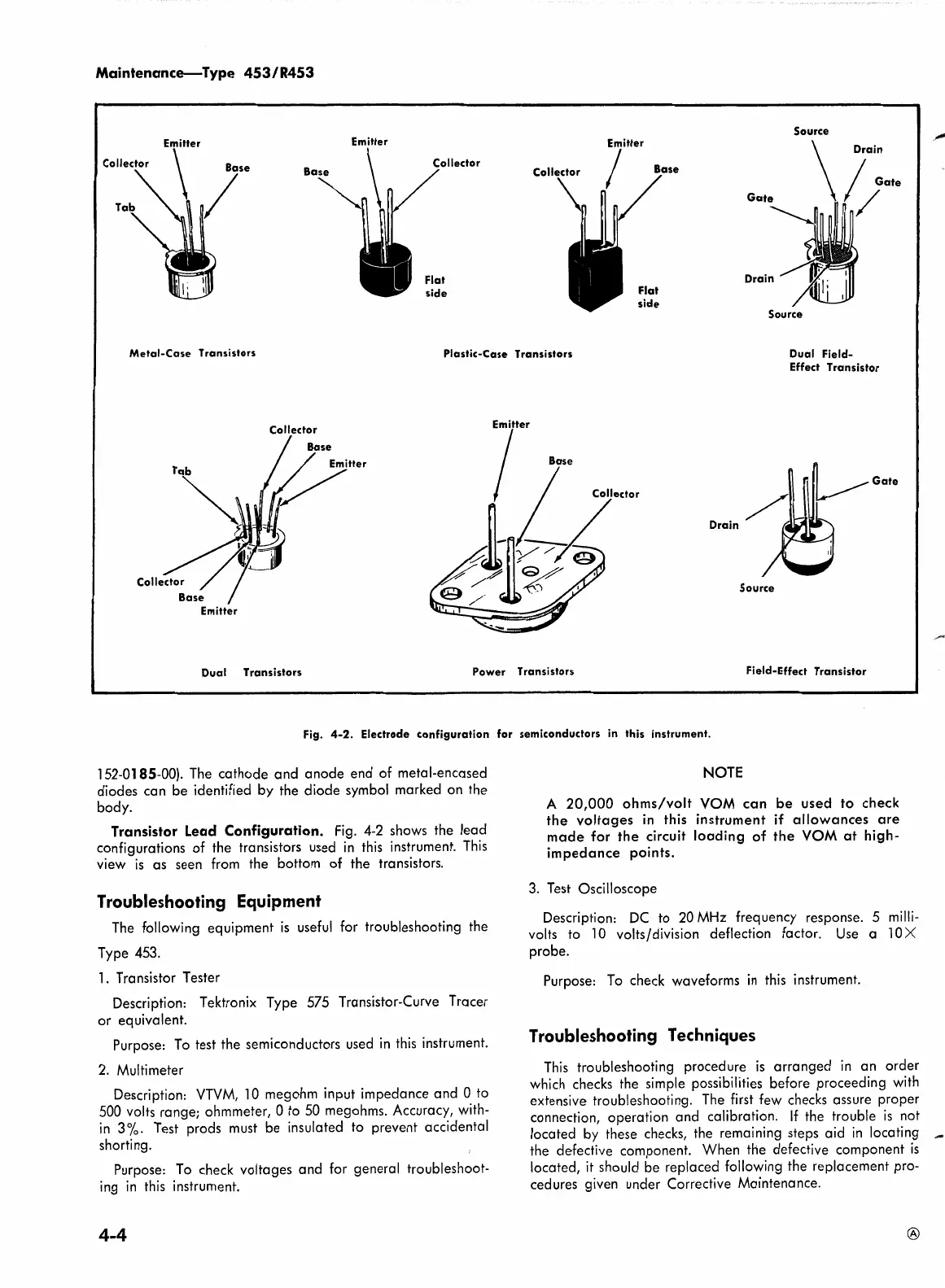
Fig.
4-2.
Electrode
configuration
for
semiconductors
in
this
instrument.
152-0185-00).
The
cathode and anode end of metal-encased
diodes can be identified by the diode symbol marked on the
body.
Transistor Lead
Configuration.
Fig.
4-2
shows the lead
configurations of the transistors used
in
this
instrument.
This
view
is
as seen
from
the bottom of the transistors.
Troubleshooting Equipment
The
following equipment
is
useful
for troubleshooting the
Type 453.
1.
Transistor Tester
Description: Tektronix Type
575
Transistor-Curve Tracer
or equivalent.
Purpose:
To
test the semiconductors used
in
this
instrument.
2.
Multimeter
Description:
VTVM,
10
megohm input impedance and 0
to
500
volts range; ohmmeter, 0 to
50
megohms. Accuracy, with-
in
3%. Test prods
must
be insulated to prevent accidental
shorting.
Purpose:
To
check voltages and for general troubleshoot-
ing
in
this
instrument.
4-4
NOTE
A
20,000
ohms/volt
VOM
can
be
used to check
the
voltages
in
this instrument
if
allowances
are
made
for
the
circuit
loading
of
the
VOM
at
high-
impedance
points.
3.
Test Oscilloscope
Description:
DC
to
20
MHz
frequency response. 5
milli-
volts to
10
volts/division deflection factor.
Use
a
lOX
probe.
Purpose:
To
check waveforms
in
this
instrument.
Troubleshooting Techniques
This
troubleshooting procedure
is
arranged
in
an order
which checks the simple possibilities before proceeding with
extensive troubleshooting.
The
first
few checks assure proper
connection, operation and calibration.
If the trouble
is
not
located by these checks, the remaining steps aid
in
locating
the defective component. When the defective component
is
located,
it
should be replaced following the replacement pro-
cedures given under Corrective Maintenance.
®