Performance
Check/Calibration-Type
453/R453
•
•
!
__
•
'·'
·l
I~
I
'
' '
'·
~
~
'
"
--
j
~
r r
-,
, ,
,
r
··r
r
r
0.5
division
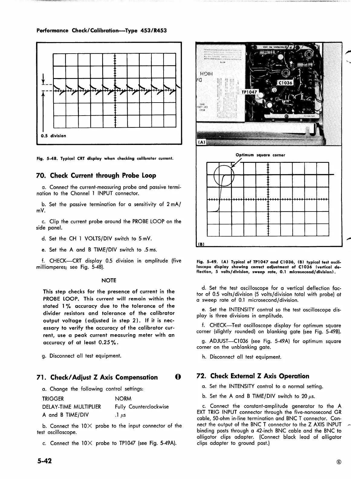
Fig.
5-48.
Typic;al
CRT
display
when
checking
calibrator
current.
70. Check Current through Probe
Loop
a.
Connect
the
current-measuring
probe
and
passive termi-
nation to
the
Channel l INPUT connector.
b. Set
the
passive termination for a sensitivity
of
2
mA/
mV.
c. Clip
the
current
probe
around
the
PROBE
LOOP on
the
side
panel.
d. Set
the
CH
l VOLTS/DIV switch
to
5
mV.
e. Set
the
A
and
B TIME/DIV switch
to
.5
ms.
f.
CHECK-CRT
display 0.5 division m
amplitude
(five
milliamperes;
see
Fig. 5-48).
NOTE
This
step
checks
for
the
presence
of
current
in
the
PROBE LOOP. This
current
will
remain
within
the
stated
l %
accuracy
due
to
the
tolerance
of
the
divider
resistors
and
tolerance
of
the
calibrator
output
voltage
(adjusted
in
step
2).
If it
is
nec-
essary
to
verify
the
accuracy
of
the
calibrator
cur-
rent,
use
a
peak
current
measuring
meter
with
an
accuracy
of
at
least
0.25
% .
g. Disconnect all test equipment.
71. Check/ Adiust Z Axis Compensation
a.
Change
the
following control settings:
TRIGGER
DELAY-TIME
MULTIPLIER
A
and
B TIME/DIV
NORM
Fully Counterclockwise
.l µs
0
b. Connect the l 0 X
probe
to
the input connector of the
test oscilloscope.
c. Connect
the
l 0 X
probe
to TPl 047 (see Fig. 5-49A).
5-42
Optimum
square
corner
(
--.....'
I?
\
\
J
_/)
I
.
.
~
(BJ
Fig.
5-49.
IA) Typical
of
TPl
047
and
Cl
036,
IBJ
typical
test
oscil-
loscope
display
showing correct
adjustment
of
Cl
036
(vertical
de-
flection, 5
volts/division,
sweep
rate,
0.1
microsecond/division).
d.
Set
the
test oscilloscope for a vertical deflection fac-
tor
of 0.5 volts/division
(5
volts/division total with probe)
at
a
sweep
rate
of
0.1
microsecond/division.
e. Set the
INTENSITY
control so
the
test oscilloscope dis-
play
is
three
divisions
in
amplitude.
.f.
CHECK-Test
oscilloscope
display
for optimum
square
corner (slightly rounded) on blanking
gate
(see Fig. 5-498).
g.
ADJUST-Cl036
(see Fig. 5-49A) for optimum
square
corner on the unblanking
gate.
h.
Disconnect all test equipment.
72. Check External Z Axis Operation
a.
Set the
INTENSITY
control to a normal setting.
b. Set
the
A
and
B TIME/DIV switch
to
20
µs.
c.
Connect
the
constant-amplitude
generator
to
the
A
EXT
TRIG
INPUT
connector through
the
five-nanosecond
GR
cable,
50-ohm in-line termination
and
BNC T connector. Con-
nect the
output
of the
BNC
T connector
to
the
Z
AXIS
INPUT
binding posts through a 42-inch BNC
cable
and
the BNC
to
alligator
clips
adapter.
(Connect black
lead
of
alligator
clips
adapter
to ground post.)
©
 Loading...


