Circuit
Description-Type
453/R453
Auto
Multivibrator
Q485,
Q494
Q495
Auto
gate
to
A
Sweep
Generator
Trigger T D
0475
Trigger
pulse
to
A
Sweep
Generator
A
trigger
SW430
signal
I
SOURCE
from Trigger
.._
___
__,
Preamp
SW435
I COUPLING I
I
I
I
I
I
I
Slope
Comparator
Q454,
Q464
\
R460
EXT
TRIG
INPUT
\
\
\
I
S~OPE
I
SW455
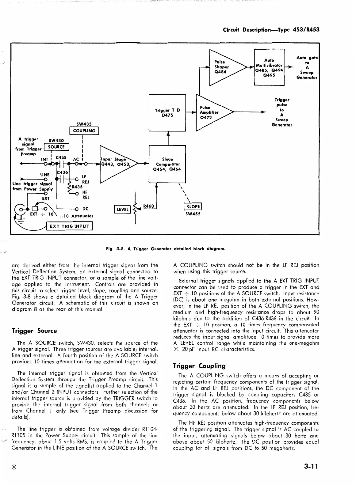
Fig.
3-8.
A Trigger
Generator
detailed
block
diagram.
are derived either from the internal trigger signal from the
Vertical Deflection System, an external signal connected to
the
EXT
TRIG
INPUT connector,
or
a sample
of
the line volt-
age
applied
to the instrument. Controls are provided in
this circuit to select trigger level, slope, coupling and source.
Fig. 3-8 shows a detailed block diagram
of
the A Trigger
Generator circuit. A schematic
of
this circuit
is
shown on
diagram 8
at
the rear
of
this manual.
Trigger Source
The
A
SOURCE
switch, SW430, selects the source
of
the
A trigger signal. Three trigger sources are available; internal,
line and external. A fourth position
of
the A
SOURCE
switch
provides
10
times attenuation for the external trigger signal.
The
internal trigger signal
is
obtained from the Vertical
Deflection
System
through the Trigger Preamp circuit.
This
signal
is
a sample
of
the signal(s)
applied
to the Channel 1
and/or
Channel 2 INPUT connectors. Further
selec+ion
of
the
internal trigger source
is
provided by the
TRIGGER
switch to
provide the internal trigger signal from both channels or
from Channel 1 only
(see
Trigger Preamp discussion for
details).
The
line trigger
is
obtained from voltage divider
Rl
104-
Rl
105 in the Power Supply circuit.
This
sample
of
the line
frequency,
about
1.5 volts
RMS,
is
coupled to the A Trigger
Generator in the LINE position
of
the A
SOURCE
switch.
The
®
A COUPLING switch should not be in the
LF
REJ
position
when using this trigger source.
External
trigger
signals
applied
to the A
EXT
TRIG
INPUT
connector can be
used
to produce a trigger in the
EXT
and
EXT
....;-
10
positions
of
the A
SOURCE
switch. Input resistance
(DC)
is
about
one megohm
in
both external positions. How-
ever, in the
LF
REJ
position
of
the A COUPLING switch, the
medium and high-frequency resistance drops to
about
90
kilohms due to the addition
of
C436-R436 in the circuit.
In
the
EXT
....;-
10 position, a
10
times frequency compensated
attenuator
is
connected into the input circuit.
This
attenuator
reduces the input signal amplitude
10
times to provide more
A
LEVEL
control range while maintaining the one-megohm
X
20
pF
input
RC
characteristics.
Trigger Coupling
The
A COUPLING switch offers a
means
of
accepting or
rejecting certain frequency components
of
the trigger signal.
In
the AC and
LF
REJ
positions, the
DC
component
of
the
trigger signal
is
blocked
by
coupling capacitors C435 or
C436.
In
the AC position, frequency components below
about
30
hertz are attenuated.
In
the
LF
REJ
position, fre-
quency components
below
about
30
kilohertz are attenuated.
The
HF
REJ
position attenuates high-frequency components
of
the triggering signal.
The
trigger signal
is
AC coupled to
the input, attenuating signals below
about
30
hertz and
above
about
50
kilohertz.
The
DC position provides equal
coupling for all signals from
DC
to
50
megahertz.
3-11
 Loading...


