, Performance Check/Calibration-Type
453/R453
Standard
amplitude·
calibrator
i
·>\,;p;<········
•
\.~~or\
50-ohm 50-ohm
BNC
in-line
termination termination
Time-mark
generator
\
~at
input·
'\
coupler
B~C
to.
18-inch
alligator BNC cable
clips
adapter
Test
Oscilloscope
Current·
measuring
probe
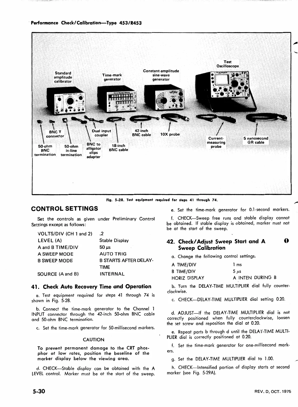
Fig. S
..
28.
Test
equipment
required for steps
41
through
74.
CONTROL SETTINGS
Set the controls
as
given under Preliminary Control
Settings except
as
follows:
VOL
TS/DIV
(CH
1
and
2)
LEVEL
(A)
A and B
TIME/DIV
A SWEEP
MODE
B
SWEEP
MODE
SOURCE
(A
and
B)
.2
Stable Display
50µs
AUTO
TRIG
B
STARTS
AFTER
DELAY-
TIME
INTERNAL
41.
Check
Auto
Recovery
Time
and Operation
a. Test equipment required for steps
41
through
74
1s
shown
in
Fig.
5-28.
b. Connect the time-mark generator to the Channel 1
INPUT
connector through the 42-inch 50-ohm
BNC
cable
and 50-ohm
BNC
termination.
c.
Set the time-mark generator for
SO-millisecond
markers.
CAUTION
To
prevent
permanent
damage
to
the
CRT
phos-
phor
at
low rates, position
the
baseline
of
the
marker
display
below
the
viewing
area.
d.
CHECK-Stable display can be obtained
with
the A
~EVEL
control. Marker
must
be
at
the start
of
the sweep.
5-30
e. Set the time-mark generator for 0.1-second markers.
f.
CHECK-Sweep free
runs
and stable display cannot
be obtained.
If
stable display
is
obtained, marker
must
not
be
at
the start of the sweep.
42. Check/ Adiust Sweep Start and A 0
Sweep Calibration
a. Change the following control settings:
A
TIME/DIV
B
TIME/DIV
HORIZ
DISPLAY
1
ms
5 µs
A
INTEN
DURING
B
b.
Turn
the
DELAY-TIME
MULTIPLIER
dial
fully
counter-
clockwise.
c.
CHECK-DELAY-TIME
MULTIPLIER
dial setting 0.20.
d.
ADJUST-If the
DELAY-TIME
MULTIPLIER
dial
is
not
correctly positioned when
fully
counterclockwise, loosen
the set screw and reposition the dial
at
0.20.
e. Repeat parts b through d
until
the
DELAY-TIME
MUL
Tl-
PLIER
dial
is
correctly positioned
at
0.20.
f.
Set the time-mark generator for one-millisecond mark-
ers.
g.
Set the
DELAY-TIME
MULTIPLIER
dial to
1.00.
h.
CHECK-Intensified portion of display starts
at
second
marker (see
Fig.
5-29A).
REV.
D, OCT.
1975
 Loading...


