Operating
Instructions-Type
453/R453
NOTE
To
check for
proper
setting
of
the
ASTIG
adjust-
ment, slowly turn
the
FOCUS
control through
the
optimum setting.
If
the
ASTIG
adjustment
is
cor-
rectly set,
the
vertical
and
horizontal portions
of
the
trace
will come into
sharpest
focus
at
the
same
position
of
the
FOCUS
control. This setting
of
the
ASTIG
adjustment
should
be
correct for
any
display. However, it
may
be
necessary to reset
the
FOCUS
control slightly
when
the
INTENSITY
control
is
changed.
1.
Connect a 1 V Calibrator signal
to
either channel and
set the
VOLTS/DIV
switch of that
channe·I
to
present a two-
division display. Set the
MODE
switch to display the chan-
nel
selected.
2.
Set the
TIME/DIV
switch to
.2
ms.
3.
With the
FOCUS
control and
ASTIG
adjustment set to
midrange, adjust the
INTENSITY
control so the
rising
portion
of the display can
be
seen.
4.
Set the
ASTIG
adjustment so the horizontal and verti-
cal portions of the display are equally focused, but not
necessarily well focused.
5.
Set the
FOCUS
control
so
the vertical portion of the
trace
is
as thin as possible.
6.
Repeat steps 4 and 5 for best overall
focus.
Make
final
check
at
normal intensity.
Graticule
The
graticule of the Type
453
is
internally marked on the
faceplate of the
CRT
to
provide accurate, no-parallax meas-
urements.
The
graticule
is
marked
with
six
vertical and
10
horizontal divisions.
Each
division
is
0.8
centimeter square:
In
addition, each major division
is
divided into
five
minor
divisions
at
the center vertical and horizontal
lines.
The
vertical gain and horizontal timing are calibrated
to
the
graticule
so
accurate measurements can be made
from
the
CRT.
The
illumination of the graticule
lines
can be varied
with
the
SCALE
ILLUM
control.
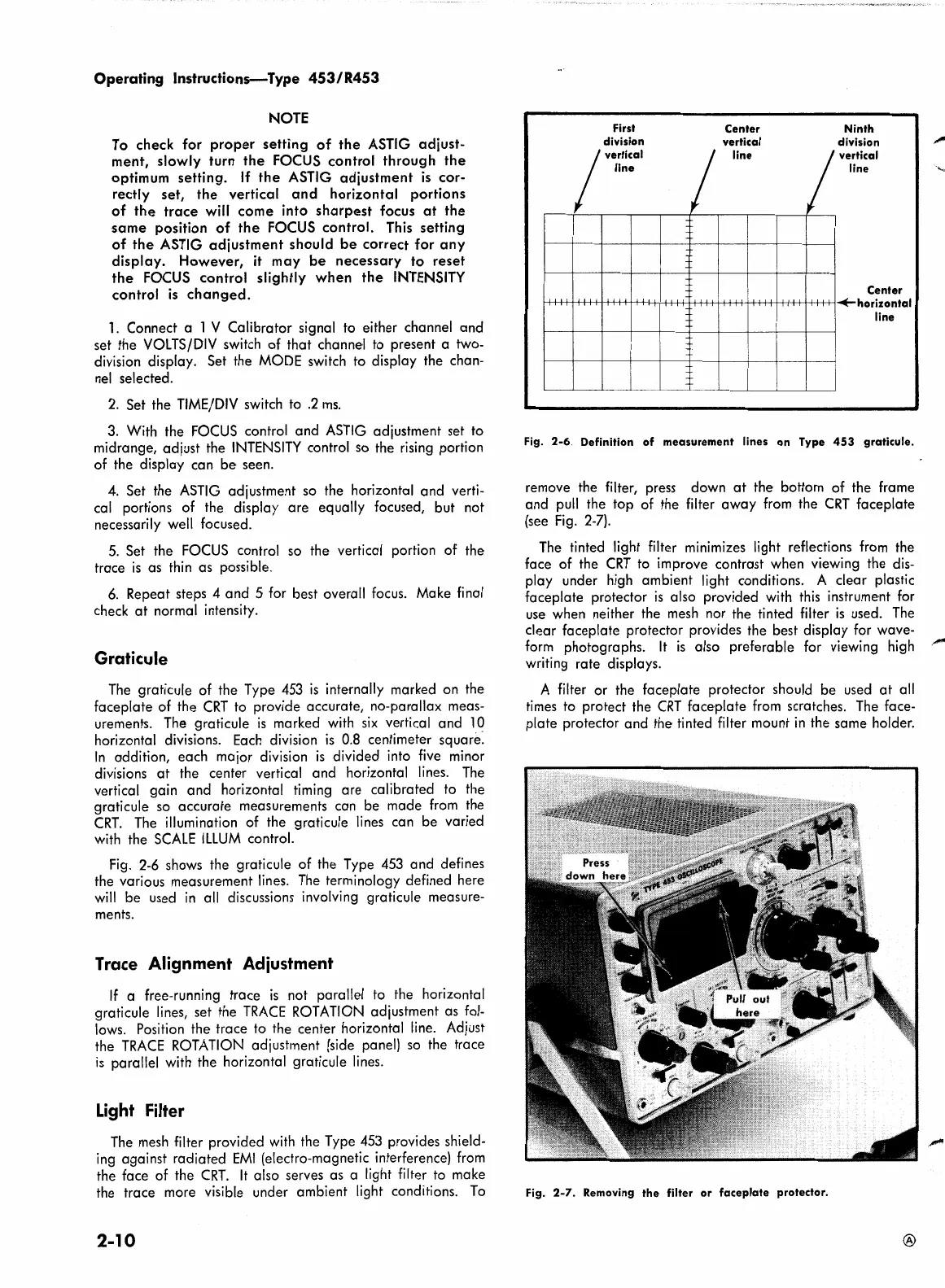
Fig.
2-6
shows the graticule of the Type
453
and defines
the various measurement
lines.
The
terminology defined here
will
be used
in
all
discussions involving graticule measure-
ments.
Trace
Alignment
Adiustment
If
a free-running trace
is
not parallel to the horizontal
graticule
lines,
set the
TRACE
ROTATION
adjustment as
fol-
lows.
Position the trace
to
the center horizontal
line.
Adjust
the
TRACE
ROTATION
adjustment
(side
panel)
so
the trace
is
parallel
with
the horizontal graticule
lines.
Light Filter
The
mesh
filter provided
with
the Type
453
provides shield-
ing
against radiated
EMI
(electro-magnetic interference)
from
the face of the
CRT.
It
also serves as a light filter
to
make
the trace more visible under ambient light conditions.
To
2-10
First
division
line
;••rllcal
-
-
-
-
-
-
Center
vertical
line
I
I
Ninth
division
vertical
line
Center
.+horizontal
line
Fig.
2-6.
Definition
of
measurement
lines
on
Type
453
graticule.
remove the filter, press down
at
the bottom of the frame
and
pull
the top of the filter away
from
the
CRT
faceplate
(see
Fig.
2-7).
The
tinted light filter minimizes light reflections
from
the
face of the
CRT
to
improve contrast when viewing the
dis-
play under
high
ambient light conditions. A clear plastic
faceplate protector
is
also provided
with
this
instrument
for
use
when neither the
mesh
nor the tinted filter
is
used.
The
clear faceplate protector provides the best display for wave-
form
photographs.
It
is
also preferable for viewing
high
writing rate displays.
A filter or the faceplate protector should be used
at
all
times
to
protect the
CRT
faceplate
from
scratches.
The
face-
plate protector and the tinted filter mount
in
the same holder.
Fig.
2-7.
Removing
the
filter
or
faceplate
protector.
®