Operating
Instructions-Type
453
/ R453
1. Set the Input Coupling switches
to
the desired coupling
positions.
2.
Set the
MODE
switch to either CHOP or
ALT.
In
gen-
eral,
CHOP
is
more suitable for low-frequency signals and
the
ALT
position
is
more suitable for high-frequency signals.
More information on determining the mode
is
given under
Dual-Trace Operation
in
this
section.
3. Set the
TRIGGER
switch to
CH
1
ONLY.
4.
Connect the reference signal
to
Channel 1
INPUT
and
the comparison signal to Channel
2
INPUT.
The
reference
signal should precede the comparison signal
in
time.
Use
coaxial cables or probes which have equal
time
delay
to
connect the signals
to
the
INPUT
connectors.
5.
If the signals
are
of opposite polarity,
pull
out the
INVERT
switch
to
invert the
Channe·I
2 display (signal may
be of opposite polarity due to 180° time difference;
if
so,
take into account
in
final calculation).
6.
Set the
VOLTS/DIV
switches to produce four-or
five-
division displays.
7.
Set the A
LEVEL
control for a stable display.
8.
If possible, set the
TIME/DIV
switch for a sweep rate
which shows three or more divisions between the two wave-
.
forms.
9.
Adjust the vertical POSITION controls
to
center each
waveform
(or
the points
on
the display between which the
measurement
is
made)
in
relation to the center horizontal
line.
10.
Adjust the horizontal
POSITION
control
so
the Chan-
nel
1 (reference) waveform crosses the center horizontal
line
at
a vertical graticule
line.
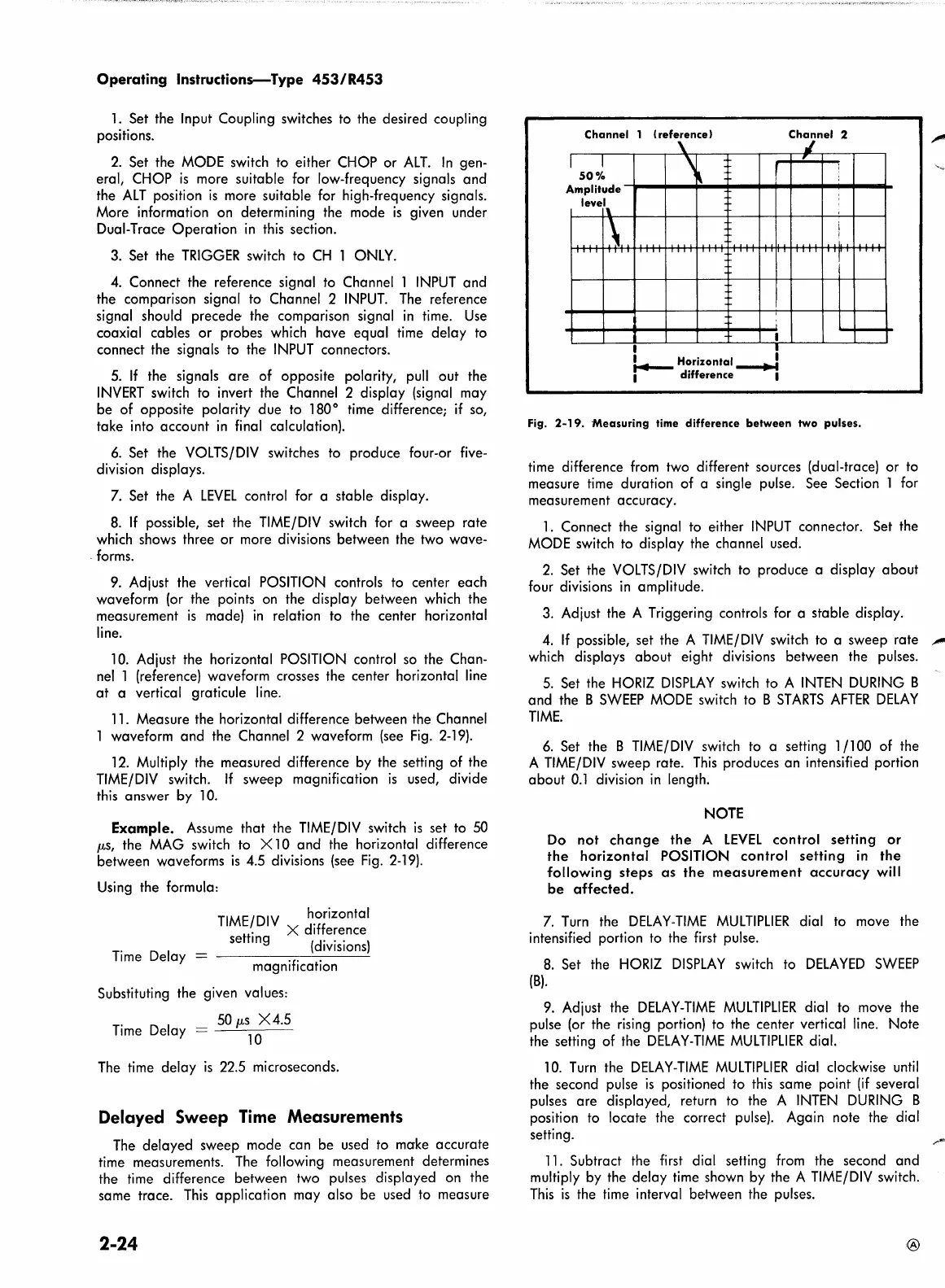
11. Measure the horizontal difference between the Channel
1 waveform and the Channel 2 waveform
(see
Fig.
2-19).
12.
Multiply the measured difference by the setting of the
TIME/DIV
switch. If sweep magnification
is
used, divide
this
answer
by
10.
Example.
Assume
that the
TIME/DIV
switch
is
set
to
50
µ,s,
the
MAG
switch
to
X
10
and the horizontal difference
between waveforms
is
4.5 divisions (see
Fig.
2-19).
Using
the formula:
TIME/DIV
h.orizontal
tf
X difference
se
mg
(divisions)
Time
Delay =
magnification
Substituting the given values:
The
time
delay
is
22.5
microseconds.
Delayed Sweep Time Measurements
The
delayed sweep mode can be used
to
make accurate
time measurements.
The
following measurement determines
the time difference between two pulses displayed on the
same trace.
This
application may also be used
to
measure
2-24
Channel
1
(reference)
I
I
50%
Amplitude
level
\
\.
111
\.
'
'
I
11
111
I
I
I
~
Horizontal __..J
I difference I
Channel
2
,/
,,
:
:
i
I
Fig.
2-19.
-Measuring time
difference
between
two pulses.
time
difference
from
two different sources (dual-trace) or to
measure
time
duration of a single pulse. See Section 1
for
measurement accuracy.
1.
Connect the signal
to
either
INPUT
connector. Set the
MODE
switch
to
display the channel used .
2.
Set the
VOLTS/DIV
switch
to
produce a display about
four divisions
in
amplitude.
3.
Adjust the A Triggering controls for a stable display.
4.
If possible, set the A
TIME/DIV
switch
to
a sweep rate
...,..
which
displays about eight divisions between the pulses.
5.
Set the
HORIZ
DISPLAY
switch to A
INTEN
DURING
B
and the B
SWEEP
MODE
switch to B
ST
ARTS
AFTER
DELAY
TIME.
6.
Set the B
TIME/DIV
switch to a setting 1/100 of the
A
TIME/DIV
sweep rate.
This
produces an intensified portion
about
0.1
division
in
length.
NOTE
Do
not
change
the
A
LEVEL
control setting
or
the
horizontal POSITION control setting
in
the
following steps
as
the
measurement
accuracy
will
be
affected.
7.
Turn
the
DELAY-TIME
MULTIPLIER
dial
to
move
the
intensified portion
to
the first pulse.
8.
Set the
HORIZ
DISPLAY
switch to
DELAYED
SWEEP
(B).
9.
Adjust the
DELAY-TIME
MULTIPLIER
dial to move the
pulse
(or
the
rising
portion) to the center vertical
line.
Note
the setting of the
DELAY-TIME
MULTIPLIER
dial.
10.
Turn
the
DELAY-TIME
MULTIPLIER
dial clockwise
until
the second pulse
is
positioned to
this
same point
(if
several
pulses are displayed, return to the A
INTEN
DURING
B
position
to
locate the correct pulse). Again note
the·
dial
setting.
11.
Subtract the
first
dial setting
from
the second and
multiply
by
the delay time shown by the A
TIME/DIV
switch.
This
is
the
time
interval be·tween the pulses.