I~
Horizontal
~I
I
distance
I
I I
Fig.
2-17.
Measuring
the
time
duration
between
points
on
a
wave-
form.
1.
Measure the
time
duration of one cycle
of
the·
wave-
form
as described
in
the previous application.
2. Take the reciprocal of the
time
duration
to
determine
the frequency.
Example.
The
frequency of the signal shown
in
Fig.
2-17
which has a
time
duration of 0.5 milliseconds
is:
Frequency
time
duration
1
-
05
= 2kHz
.
ms
Risetime Measurements
Risetime
measurements employ basically the same tech-
niques as time-duration measurements.
The
main difference
is
the points between which the measureme·nt
is
made.
The
following procedure gives the basic method of measuring
risetime between the
10% and 90% points of the waveform.
Falltime can be measured
in
the same manner
on
the trailing
edge of the waveform.
1.
Connect the signal
to
either
INPUT
connector.
2.
Set the
MODE
switch
to
display
the·
channel used.
3.
Set the
VOLTS/DIV
switch and the
VARIABLE
control
to produce a display an exact number of divisions
in
ampli-
tude.
4.
Center the display about the center horizontal
line.
5.
Set the A Triggering controls
to
obtain a stable
dis-
play.
6.
Set the
TIME/DIV
switch
to
the fastest sweep rate that
displays
less
than eight divisions between the 10% and 90%
points on the waveform.
7.
Determine the 10% and 90% points
on
the
rising
portion of the waveform.
The
figures given
in
Table 2-2 are
for the points
10%
up
from
the start of the
rising
portion
and
10%
down
from
the top of the
rising
portion (90%
point).
8.
Adjust the horizontal
POSITION
control
to
move the
10% point of the waveform
to
the
first
graticule
line.
For
@
Operating Instructions-Type
453
/ R453
Vertical
Divisions vertically
display
10%
and
90%
between
10%
&
(divisions)
points
90%
points
4
0.4
and 3.6 divisions
3'.2
5
0.5
and 3.5 divisions
4.0
6
0.6 and 3.4 divisions 4.8
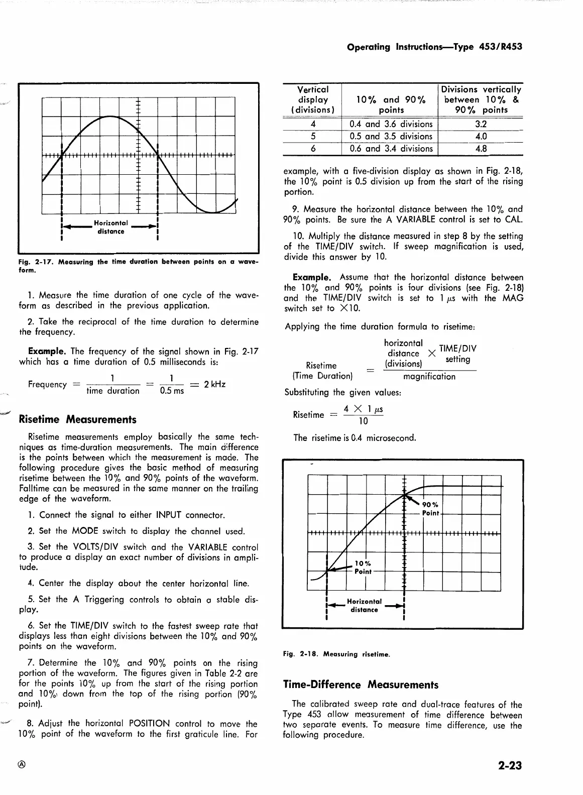
example,
with
a five-division display as shown
in
Fig.
2-18,
the 10% point
is
0.5 division
up
from
the start of the
rising
portion.
9.
Measure the horizontal distance between the 10% and
90% points.
Be
sure the A
VARIABLE
control
is
set
to
CAL.
10. Multiply the distance measured
in
step 8
by
the setting
of the
TIME/DIV
switch.
If
sweep magnification
is
used,
divide
this
answer by 10.
Example.
Assume
that the horizontal distance between
the
10% and 90% points
is
four divisions
(see
Fig.
2-18)
and the
TIME/DIV
switch
is
set
to
1
µs
with
the
MAG
switch set to X 10.
Applying the
time
duration formula
to
risetime:
Risetime
(Time
Duration)
ho.rizontal
TIME/DIV
distance X .
(divisions)
setting
magnification
Substituting the given values:
R
. .
4 X 1
µs
1set1me
=
10
The
risetime
is
0.4
microsecond.
I~
Horizontal
......:
I
distance
I
I I
Fig.
2-18.
Measuring
risetime.
Time-Difference Measurements
The
calibrated sweep rate and dual-trace features of the
Type
453
allow measurement of
time
difference between
two separate events.
To
measure
time
difference,
use
the
following procedure.
2-23