Vertical
signal
from
Delay-Line
Driver
Delay
Line
(~140
ns)
Phase
Equalizing
Network
Circuit
Description-Type 453/R453
I
I
SW330
I
I
TRACE
FINDER
Vertical
deflection
signal
to
vertical
deflection
plates
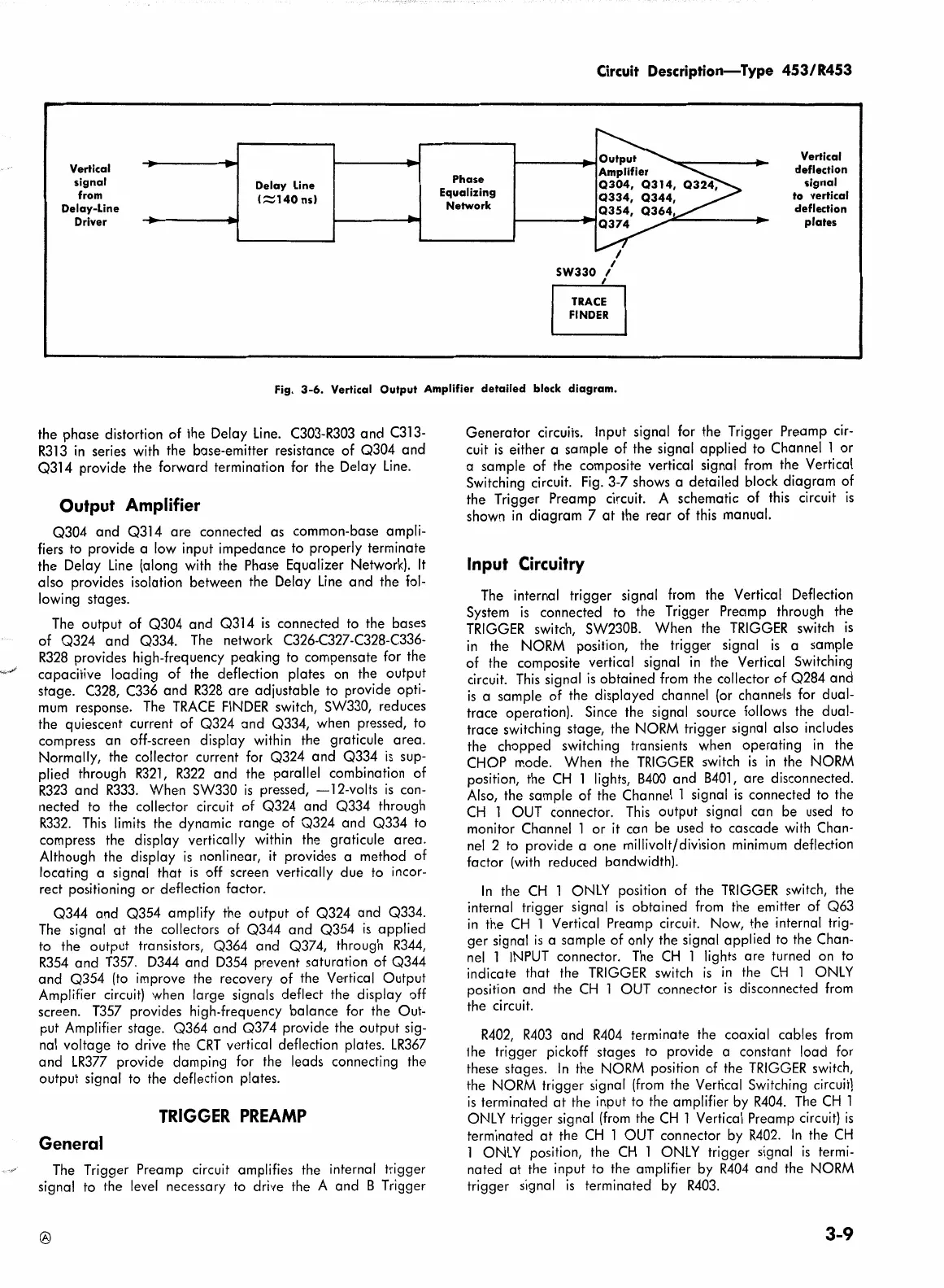
Fig.
3-6.
Vertical Output Amplifier detailed block diagram.
the phase distortion of the Delay
Line.
C303-R303
and
C313-
R313
in
series
with
the base-emitter resistance of Q304 and
Q314 provide the forward termination for the Delay
Line.
Output Amplifier
Q304 and Q314 are connected as common-base ampli-
fiers to provide a
low
input impedance to properly terminate
the Delay
Line
(along with the Phase Equalizer Network).
It
also provides isolation between the Delay
Line
and the
fol-
lowing stages.
The
output of Q304 and Q314
is
connected to the bases
of Q324 and Q334.
The
network C326-C327-C328-C336-
R328
provides high-frequency peaking to compensate for the
capacitive loading of the defledion plates
on
the output
stage.
C328,
C336
and
R328
are adjustable to provide opti-
mum
response.
The
TRACE
FINDER
switch, SW330, reduces
the quiescent current of Q324 and Q334, when pressed, to
compress an off-screen display within the graticule area.
Normally, the collector current for Q324 and Q334
is
sup-
plied through
R321,
R322
and the parallel combination of
R323
and
R333.
When SW330
is
pressed,
-12-volts
is
con-
nected to the collector circuit of Q324 and Q334 through
R332.
This
limits
the dynamic range of Q324 and Q334 to
compress the display vertically within the graticule area.
Although the display
is
nonlinear,
it
provides a method of
locating a signal that
is
off screen vertically due to incor-
rect positioning or deflection factor.
Q344 and Q354 amplify the output of Q324 and Q334.
The
signal
at
the collectors of Q344 and Q354
is
applied
to the output transistors, Q364 and Q374, through
R344,
R354
and
T357.
D344
and
D354
prevent saturation of Q344
and Q354
(to
improve the recovery of the Vertical Output
Amplifier
circuit)
when large signals deflect the display off
screen.
T357
provides high-frequency balance for the Out-
put Amplifier stage. Q364 and Q374 provide the output sig-
nal
voltage
to
drive the
CRT
vertical deflection plates.
LR367
and
LR377
provide damping for the leads connecting the
output signal to the deflection plates.
TRIGGER
PREAMP
General
The
Trigger Preamp circuit amplifies the internal trigger
signal to the
level
necessary to drive the A and 8 Trigger
®
Generator circuits. Input signal for the Trigger Preamp
cir-
cuit
is
either a sample of the signal applied to Channel 1 or
a sample of the composite vertical signal
from
the Vertical
Switching circuit.
Fig.
3-7 shows a detailed block diagram of
the Trigger Preamp circuit. A schematic of
this
circuit
is
shown
in
diagram 7
at
the rear of
this
manual.
Input Circuitry
The
internal trigger signal
from
the Vertical Deflection
System
is
connected to the Trigger Preamp through the
TRIGGER
switch, SW2308. When the
TRIGGER
switch
is
in
the
NORM
position, the trigger signal
is
a sample
of the composite vertical signal
in
the Vertical Switching
circuit.
This
signal
is
obtained
from
the collector of Q284 and
is
a sample of the displayed channel
(or
channels
for
dual-
trace operation). Since the signal source follows the dual-
trace switching stage, the
NORM
trigger signal also includes
the chopped switching transients when operating
in
the
CHOP mode. When the
TRIGGER
switch
is
in
the
NORM
position, the
CH
1 lights,
8400
and
8401,
are disconnected.
Also,
the sample of the Channel 1 signal
is
connected to the
CH
1
OUT
connector.
This
output signal can be
used
to
monitor Channel 1 or
it
can be
used
to cascade
with
Chan-
nel
2 to provide a one millivolt/division
minimum
deflection
factor
(with
reduced bandwidth).
In
the
CH
1
ONLY
position of the
TRIGGER
switch, the
internal trigger signal
is
obtained
from
the emitter of Q63
in
the
CH
1 Vertical Preamp circuit. Now, the internal trig-
ger signal
is
a sample of only the signal applied to the Chan-
nel
1
INPUT
connector.
The
CH
1 lights are turned
on
to
indicate that the
TRIGGER
switch
is
in
the
CH
1
ONLY
position and the
CH
1
OUT
connector
is
disconnected
from
the circuit.
R402,
R403
and
R404
terminate the coaxial cables
from
!he trigger pickoff stages to provide a constant load for
these stages.
In
the
NORM
position of the
TRIGGER
switch,
the
NORM
trigger signal
(from
the Vertical Switching
circuit)
is
terminated
at
the input to the amplifier
by
R404.
The
CH
1
ONLY
trigger signal
(from
the
CH
1 Vertical Preamp circuit)
is
terminated
at
the
CH
1
OUT
connector
by
R402.
In
the
CH
1
ONLY
position, the
CH
1
ONLY
trigger signal
is
termi-
nated
at
the input to the amplifier by
R404
and the
NORM
trigger signal
is
terminated by
R403.
3-9