Performance
Check/Calibration-Type 453/R453
VARIABLE
(CH
1 and
2)
Input Coupling
(CH
1 and
2)
CAL
DC
c.
Set the standard amplitude calibrator for a
fivt
.1illi-
volt square-wave output.
d.
CHECK-CRT display
five
divisions or greater
in
ampli-
tude (one millivolt/division, or
less,
minimum
deflection
factor).
1 8.
Check
Channel 1 and 2 Input Coupling
Switch
Operation
a. Set the
CH
1 and
CH
2
VOLTS/DIV
switches to
20
mV.
h. Disconnect the 18-inch
BNC
cable
from
the Channel 2
INPUT
connector and reconnect the standard amplitude cali-
brator to the Channel 2
INPUT
connector.
c.
Set the standard amplitude calibrator for a
SO-millivolt
square-wave output.
d.
Position the display
with
the Channel 2
POSITION
con-
trol
so
the bottom of the square wave
is
at
the center
hori-
zontal
line.
e. Set the Channel 2 Input Coupling switch to GND.
f.
CHECK-CRT display for straight
line
near the center
horizontal line.
g.
Set the Channel 2 Input Coupling switch to
AC.
h.
CHECK-CRT display centered about center horizontal
line.
i.
Set the
MODE
switch to
CH
1.
j.
Position the display
with
the Channel 1
POSITION
con-
trol
so
the bottom of the square wave
is
at
the center
hori-
zontal
line.
k.
Set the Channel 1 Input Coupling switch to GND.
I.
CHECK-CRT display for straight
line
near the center
horizontal
line.
m.
Set the Channel 1 Input Coupling
switch
to
AC.
n.
CHECK-CRT display centered about center horizontal
line.
19.
Check
Low-Frequency
Vertical Linearity
a. Set the Channel 1 and 2 Input Coupling switches to
DC.
b.
Position the display to the center of the graticule
with
the Channel 1
POSITION
control.
c.
Adjust the Channel 1
VARIABLE
control
for
exactly two
divisions
of
deflection.
d.
Position the top of the display to the top horizontal
line.
e.
CHECK-Compression or expansion
0.15
division or
less
(see
Fig.
5-15).
5-16
<AJ
Expansion
<BJ
-
-
·-
,_
-
(CJ
Compression
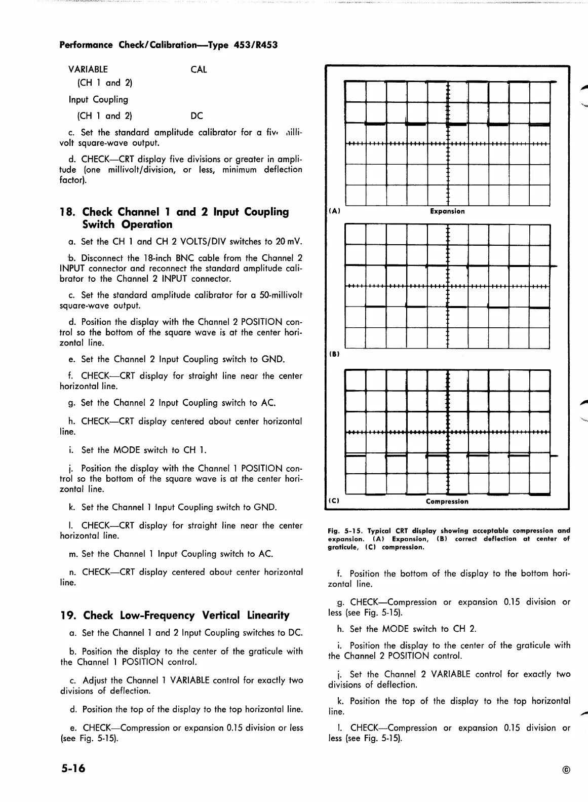
Fig.
5-15.
Typical
CRT
display
showing
acceptable
compression
and
expansion.
(A)
Expansion,
(8)
correct
deflection
at
center
of
graticule,
(CJ
compression.
f.
Position
the bottom of the display to the bottom
hori-
zontal
line.
:g.
CHECK-Compression or expansion
0.15
division or
less
(see
Fig.
5-15).
h.
Set the
MODE
switch to
CH
2.
i.
Position
the display to the center of the graticule
with
the Channel 2
POSITION
control.
j.
Set the Channel 2
VARIABLE
control for exactly two
divisions
of
deflection.
k.
Position
the top
of
the display to the top horizontal
line.
I.
CHECK-Compression or expansion
0.15
division or
less
(see
Fig.
5-15).
©
 Loading...


