Operating
Instructions-Type
453/R453
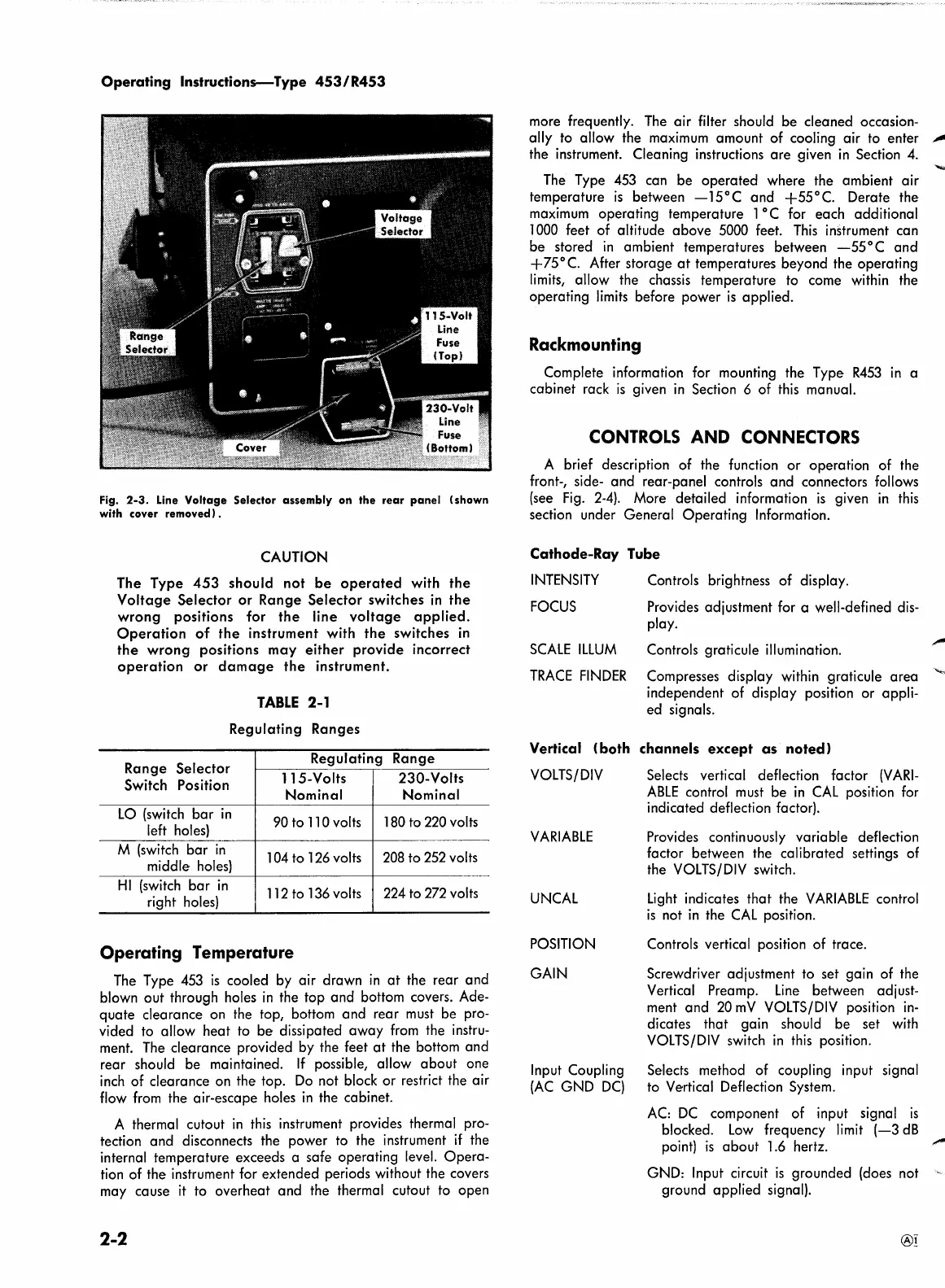
Fig.
2-3.
Line
Voltage
Selector
assembly
on
the
rear
panel
(shown
with cover removed) .
CAUTION
The Type
453 should not
be
operated
with
the
Voltage
Selector
or
Range Selector switches
in
the
wrong
positions for
the
line
voltage
applied.
Operation
of
the
instrument with
the
switches
in
the
wrong
positions may either provide incorrect
operation
or
damage
the
instrument.
TABLE
2-1
Regulating Ranges
Range Selector
Regulating
Range
115-Volts 230-Volts
Switch Position
Nominal Nominal
LO
(switch
bar
in
90to110
volts
180
to
220
volts
left holes)
M
(switch
bar
in
104
to
126
volts
208
to
252
volts
middle
holes)
HI
(switch
bar
in
112
to
136
volts
224
to
272
volts
right
holes)
Operating Temperature
The
Type
453
is
cooled
by
air drawn
in
at
the rear and
blown out through holes
in
the top and bottom covers. Ade-
quate clearance on the top, bottom and rear
must
be pro-
vided to allow heat to be dissipated away
from
the instru-
ment.
The
clearance provided by the feet
at
the bottom and
rear should be maintained.
If possible, allow about one
inch
of clearance on the top.
Do
not block or restrict the air
flow
from
the air-escape holes
in
the cabinet.
A thermal cutout
in
this
instrument provides thermal pro-
tection and disconnects the power to the instrument
if
the
internal temperature exceeds a safe operating level. Opera-
tion of the instrument for extended periods without the covers
may cause
it
to overheat and the thermal cutout to open
2-2
more frequently.
The
air filter should be cleaned occasion-
ally
to
allow the
maximum
amount of cooling air
to
enter
,,_
the instrument. Cleaning instructions are given
in
Section
4.
The
Type
453
can be operated where the ambient air
temperature
is
between
-15°C
and
+55°C.
Derate the
maximum
operating temperature 1 °C for each additional
1000
feet of altitude above 5000 feet.
This
instrument can
be stored
in
ambient temperatures between
-55°C
and
+75°C.
After storage
at
temperatures beyond the operating
limits,
allow the chassis temperature
to
come within the
operating
limits
before power
is
applied.
Rackmounting
Complete information for mounting the Type
R453
in
a
cabinet rack
is
given
in
Section 6 of
this
manual.
CONTROLS
AND
CONNECTORS
A brief description of the function or operation of the
front-, side- and rear-panel controls and connectors follows
(see
Fig.
2-4).
More de·tailed information
is
given
in
this
section under General Operating Information.
Cathode-Ray Tube
INTENSITY
Controls brightness of display.
FOCUS
SCALE
ILLUM
TRACE
FINDER
Provides adjustment for a well-defined
dis-
play.
Controls graticule illumination.
Compresses display within graticule area
""""
independent of display position or appli-
ed signals.
Vertical
(both
channels
except
as
noted)
VOLTS/DIV
VARIABLE
UN
CAL
POSITION
GAIN
Input Coupling
(AC
GND
DC)
Selects vertical deflection factor
(VARI-
ABLE
control
must
be
in
CAL
position
for
indicated deflection factor).
Provides continuously variable deflection
factor between the calibrated settings of
the
VOLTS/DIV
switch.
Light
indicates that the
VARIABLE
control
is
not
in
the
CAL
position.
Controls vertical position of trace.
Screwdriver adjustment to set gain of the
Vertical Preamp.
Line
between adjust-
ment and
20
mV
VOLTS/DIV
position
in-
dicates that gain should be set
with
VOLTS/DIV
switch
in
this
position.
Selects method of coupling input signal
to
Vertical Deflection System.
AC:
DC
component of input signal
is
blocked.
Low
frequency
limit
(-3
dB
point)
is
about 1.6 hertz.
GND: Input circuit
is
grounded (does not
ground applied signal).
 Loading...


