Performance
Check/Calibration-Type
453/R453
f.
Return the autotransformer output
voltage
to the center
of the regulating
range
selected by the
Line
Voltage Selector
assembly.
5. Adiust
CRT
Grid Bias
0
a.
Connect the precision
DC
voltmeter from
TPl
047
(Z
Axis Amplifier
board;
see
Fig. 5-4)
to
chassis ground.
b. Set the A
SWEEP
MODE switch
to
SINGLE
SWEEP.
c. Set the
INTENSITY
control for a meter reading
of
+ 12
volts.
d.
ADJUST-Crt
Grid Bias adjustment,
R940
(see Fig. 5-4),
so the
spot
just
disappears
(it
may
be
necessary to turn the
horizontal POSITION control clockwise
to
bring the
spot
onto the viewing area).
CAUTION
Do
not
allow
a
bright
spot
to
remain
stationary
for
an
extended
period,
as
it
may
burn
the
CRT
phosphor.
e. INTERACTION-Check steps 65, 71,
and
72.
f.
Disconnect the precision
DC
voltmeter.
6. Check
Low
Voltage Power Supply Ripple
NOTE
This
step
also
checks
regulation
of
the
low-voltage
supplies.
a.
Connect
the
1 X
probe
to
the test oscilloscope input.
b. Set the test oscilloscope for a vertical deflection of
0.005 volts/division, AC coupled,
at
a
sweep
rate
of five
milliseconds/division. Use line-frequency triggering
to
pro-
duce
a
stable
display.
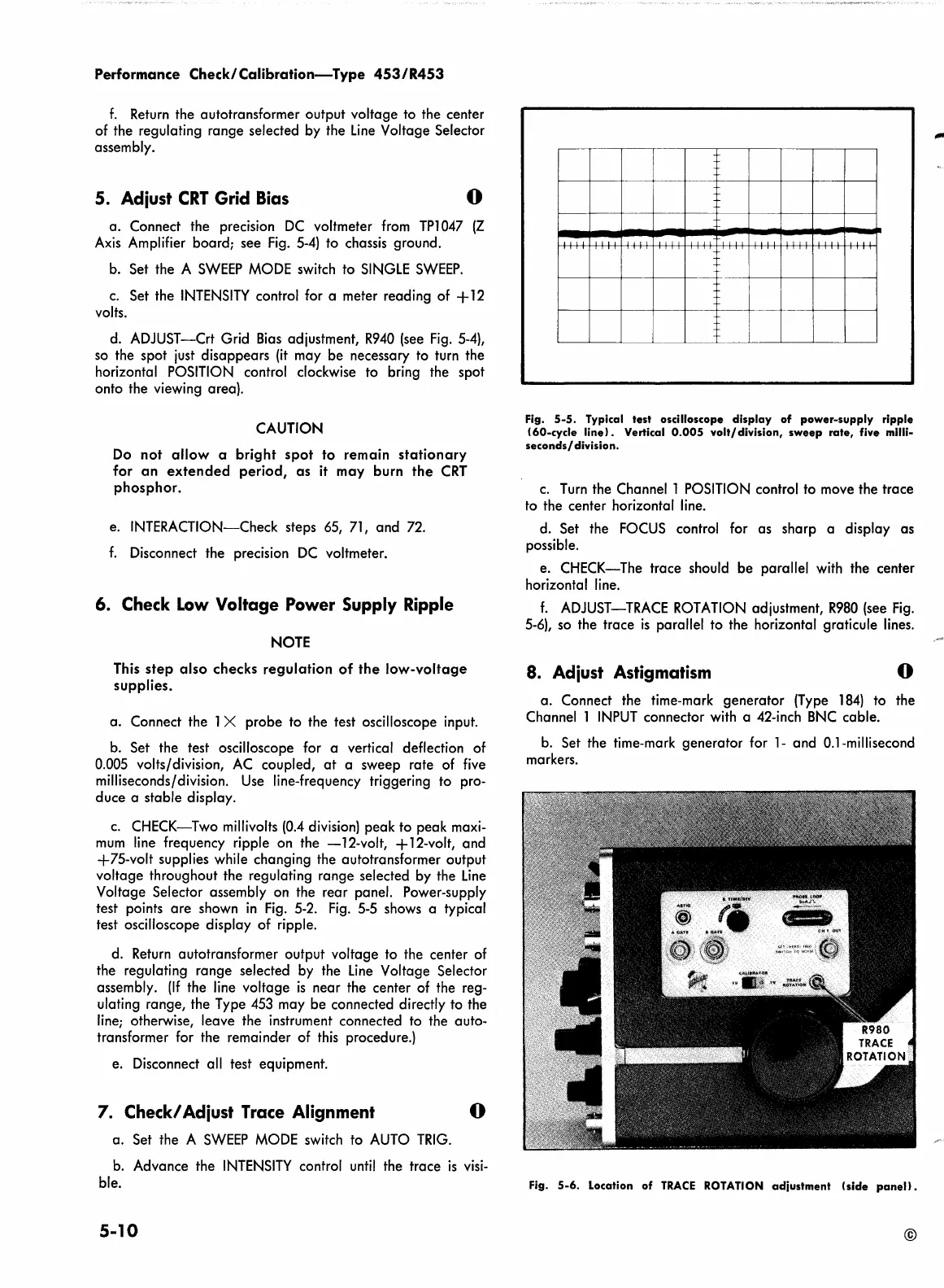
c.
CHECK-Two
millivolts (0.4 division)
peak
to
peak
maxi-
mum
line frequency ripple
on
the
-12-volt,
+ 12-volt,
and
+75-volt
supplies while changing the autotransformer output
voltage
throughout the regulating
range
selected by the
Line
Voltage Selector assembly on the
rear
panel. Power-supply
test points
are
shown
in
Fig. 5-2. Fig. 5-5 shows a typical
test oscilloscope display
of
ripple.
d. Return autotransformer output
voltage
to the center of
the regulating
range
selected by the
Line
Voltage Selector
assembly.
(If
the line
voltage
is
near
the center of the reg-
ulating
range,
the Type 453 may
be
connected directly to the
line; otherwise, leave
the
instrument connected to the auto-
transformer for the remainder of this procedure.)
e. Disconnect all test equipment.
7.
Check/
Adiust Trace Alignment
0
a.
Set the A
SWEEP
MODE switch
to
AUTO
TRIG.
b. Advance the
INTENSITY
control until the
trace
is
visi-
ble.
5-10
I
II
I I
II
I
II
Jill
I
Fig.
5-5.
Typical test oscilloscope
display
of
power-supply
ripple
(60-cycle
line).
Vertical
0.005
volt/division,
sweep
rate,
five milli-
seconds/
division.
c.
Turn the Channel 1 POSITION control to move the
trace
to the center horizontal line.
d. Set the FOCUS control for
as
sharp
a display
as
possible.
e.
CHECK-The
trace
should
be
parallel with the center
horizontal line.
f.
ADJUST-TRACE ROTATION adjustment,
R980
(see
Fig.
5-6), so the trace
is
parallel
to
the horizontal graticule lines.
8. Adiust Astigmatism
0
a.
Connect the time-mark
generator
(Type
184)
to
the
Channel 1
INPUT
connector with a 42-inch BNC cable.
b. Set the time-mark
generator
for
1-
and
0.1-millisecond
markers.
Fig.
5-6.
Location
of
TRACE
ROTATION
adjustment
(side
panel>.
©
 Loading...


