Operating lnstruction5--Type
453/R453
play appears as a diagonal straight
line,
the
two
signals are
either
in
phase (tilted upper right
to
lower
left)
or 180° out
of phase (tilted upper left
to
lower
right).
If
the display
is
a circle, the signals are 90° out of phase.
Fig.
2-27
shows
the lissajous displays produced between 0° and 360°. Notice
that above 180° phase shift, the resultant display
is
the same
as
at
some lower angle.
7.
Substract the inherent phase shift
from
the phase angle
q,
to obtain the actual phase difference.
Example.
Assume
an inherent phase difference of 2°
with
a display as shown
in
Fig.
2-26
where A
is
5
divisions
and
B
is
10
divisions.
Using
the formula:
S
. A
me
q,
= B
Substituting the given values:
Sine
q,
=
1
5
0
= 0.5
From
the trigonometric tables:
"'
= 30°
Common-Mode Reiection
The
ADD
feature of the
Type
453
can
be
used
to
display
signals
which
contain undesirable components.
These
un-
desirable components can be eliminated through
common-
mode rejection.
The
precautions given under Algebraic
Addition should be observed.
I
I
~
..
~
-
~
,
Line
'
/
'
/
frequency
'I'
~
'
"
--
....
-
I
-
Desi
1
red
signal
--
I'
/
'
,
I
'
,
'
/
'
~7
'-.
-
I
-.
,
-
_,
I
1.
Connect the signal containing both the desired and
undesired information
to
the Channel 1
INPUT
connector.
2.
Connect a signal similar to the unwanted portion of
the Channel 1 signal
to
the Channel 2
INPUT
connector.
For
example,
in
Fig.
2-28
a line-frequency signal
is
connected
to Channel 2
to
cancel out the line-frequency component of
the Channel 1 signal.
3.
Set both
Input
Coupling switches
to
DC
(AC
if
DC
component of input signal
is
too large).
4.
Set the
MODE
switch
to
ALT.
Set the
VOL
TS/DIV
switches
so
the signals are about equal
in
amplitude.
5.
Set
th~
TRIGGER
switch
to
NORM.
6.
Set the
MODE
switch
to
ADD.
Pull
the
INVERT
switch
so
the common-mode signals are of opposite polarity.
7.
Adjust the
CH
2
VOLTS/DIV
switch
and
VARIABLE
con-
trol
for
maximum
cancellation of the common-mode signal.
8.
The
signal
which
remains should be
only
the desired
portion of the Channel 1 signal.
The
undesired signal
is
cancelled out.
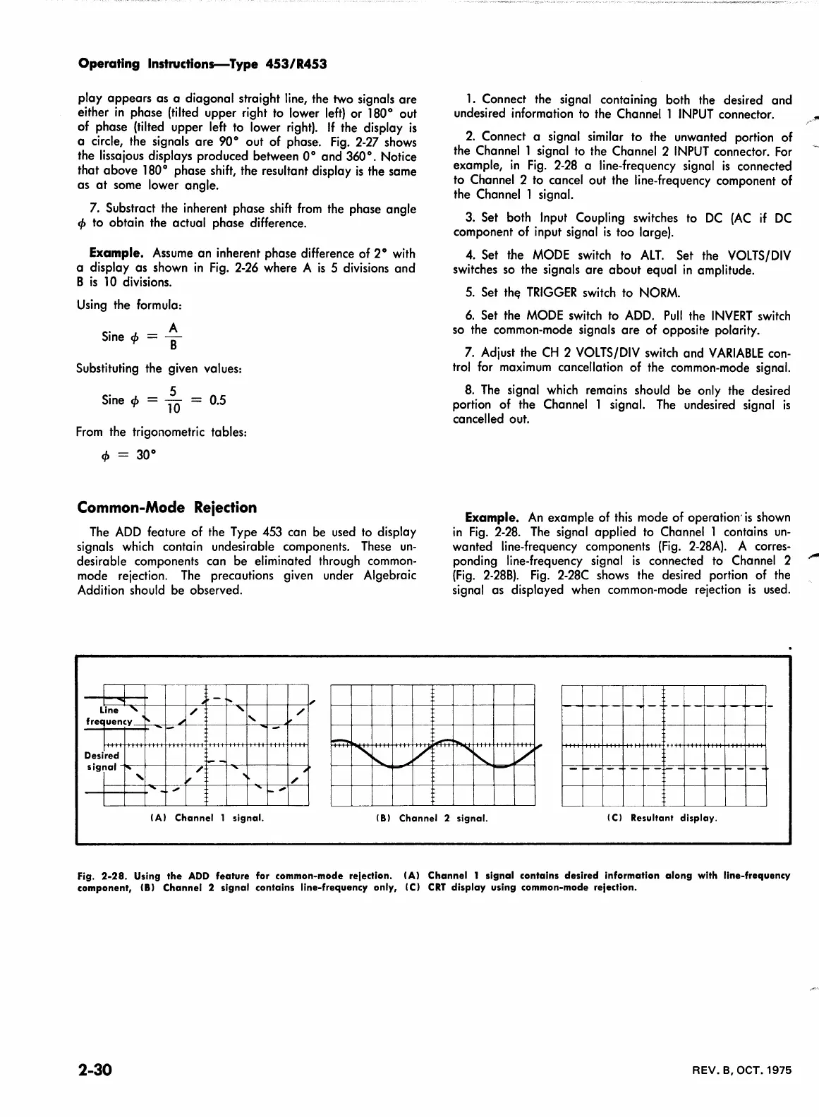
Example.
An
example
of
this
mode of operation'
is
shown
in
Fig.
2-28.
The
signal applied
to
Channel 1 contains
un-
wanted line-frequency
compone·nts
(Fig.
2-28A).
A corres-
ponding line-frequency signal
is
connected to Channel 2
(Fig.
2-288).
Fig.
2-28C
shows
the desired portion of
the
signal as displayed when common-mode rejection
is
used.
------~-
-
...
-
..
-
--~---------~~---i-
•
.-
....
"""'
'
/r
H++~H++++H+++H-++++Htt
++H-+++l+++H-++++H-++H
-
I A I
Channel
1
signal.
181
Channel 2 signal.
ICI Resultant
display.
fig.
2-28.
Using
the
ADD
feature
for common-mode reiection. IAI
Channel
1
signal
contains
desired
information
along
with line-frequency
component, IBI
Channel
2
signal
contains line-frequency only, IC)
CRT
display
using common-mode rejection.
2-30
REV.
B, OCT. 1975