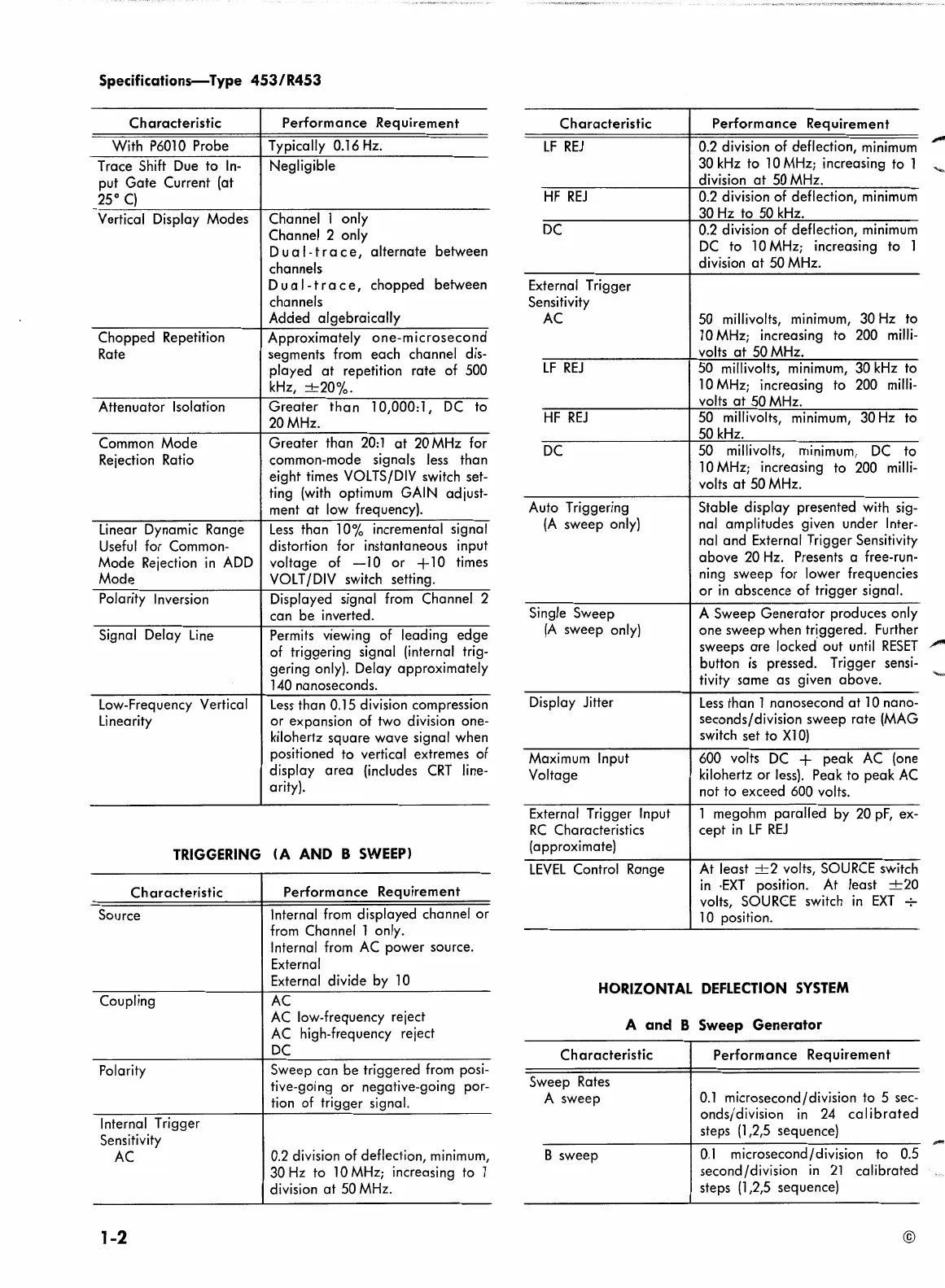
Specifications-Type
453
/ R453
Characteristic Performance Requirement
With
P6010
Probe
Typically 0.16
Hz.
Trace Shift
Due
to
In-
Negligible
put
Gate
Current (at
25°
C)
Vertical Display Modes
Channel 1 only
Channel 2 only
Dual-trace,
alternate between
channels
Dual-trace,
chopped between
channels
Added algebraically
Chopped Repetition
Approximately
one-microsecond
Rate
segments
from
each channel dis-
played
at
repetition rate of 500
kHz,
-+-20%.
Attenuator Isolation Greater
than
10,000:
l,
DC
to
20MHz.
Common Mode
Greater than
20:
l
at
20
MHz
for
Rejection Ratio
common-mode
signals
less
than
eight times
VOLTS/DIV
switch set-
ting
(with
optimum GAIN adjust-
ment
at
low
frequency).
Linear Dynamic Range
Less
than 10% incremental signal
Useful
for Common-
distortion for instantaneous input
Mode Rejection
in
ADD
voltage of
-10
or
+10
times
Mode
VOLT
/DIV
switch setting.
Polarity Inversion Displayed signal
from
Channel 2
can be inverted.
Signal Delay
Line
Permits viewing of leading edge
of triggering signal (internal trig-
gering only). Delay approximately
140
nanoseconds.
Low-Frequency Vertical
Less
than 0.15 division compression
Linearity
or expansion of two division one-
kilohertz square wave signal when
positioned to vertical extremes of
display
area
(includes
CRT
line-
arity).
TRIGGERING
<A
AND B
SWEEP>
Characteristic
Source
Coupling
Polarity
Internal Trigger
Sensitivity
AC
1-2
Performance Requirement
Internal
from
displayed channel or
from
Channel l only.
Internal
from
AC
power source.
External
External divide by
10
AC
AC
low-frequency reject
AC
high-frequency reject
DC
Sweep can be triggered
from
posi-
tive-going or negative-going por-
tion of trigger signal.
0.2
division of deflection,
minimum,
30
Hz
to l 0
MHz;
increasing to l
division
at
50
MHz.
Characteristic
LF
REJ
HF
REJ
DC
External Trigger
Sensitivity
AC
LF
REJ
HF
REJ
DC
Auto Triggering
(A
sweep only)
Single Sweep
(A
sweep
only)
Display Jitter
Maximum Input
Voltage
External Trigger Input
RC
Characteristics
(approximate)
LEVEL
Control Range
Performance Requirement
0.2
division of deflection,
minimum
,,,,_
30
kHz
to
lO
MHz;
increasing to 1
division
at
50
MHz.
0.2
division of deflection,
minimum
30
Hz
to 50
kHz.
0.2
division of deflection,
minimum
DC
to l 0
MHz;
increasing to 1
division
at
50
MHz.
50
millivolts, minimum,
30
Hz
to
l
0
MHz;
increasing to
200
milli-
volts
at
50
MHz.
50 millivolts, minimum, 30
kHz
to
10
MHz;
increasing to
200
milli-
volts
at
50
MHz.
50
millivolts, minimum, 30
Hz
to
50
kHz.
50 millivolts,
minimum,
DC
to
lO
MHz;
increasing to
200
milli-
volts
at
50
MHz.
Stable display presented with sig-
nal amplitudes given under Inter-
nal
and External Trigger Sensitivity
above
20
Hz.
Presents a free-run-
ning
sweep for lower frequencies
or
in
abscence of trigger signal.
A Sweep Generator produces only
one sweep when triggered. Further
sweeps
are
locked out
until
RESET
,,,,-
button
is
pressed. Trigger sensi-
tivity same as given above.
Less
than l nanosecond
at
lO
nano-
seconds/division sweep rate
(MAG
switch set to
Xl
0)
600 volts
DC
+ peak
AC
(one
kilohertz or
less).
Peak to peak
AC
not to exceed 600 volts.
l megohm paralled by
20
pf, ex-
cept
in
LF
REJ
At
least
-+-2
volts,
SOURCE
switch
in
·EXT
position.
At
least
-+-20
volts,
SOURCE
switch
in
EXT
-:-
10
position.
HORIZONTAL
DEFLECTION
SYSTEM
A and B
Sweep
Generator
Characteristic
Sweep
Rates
A sweep
B sweep
Performance Requirement
O.l
microsecond/division to 5 sec-
onds/division
in
24
calibrated
steps
(l
,2,5 sequence}
O.l
microsecond/division to
0.5
second/division
in
21
calibrated
steps
(1,2,5
sequence)
©
-
 Loading...


