Fig.
5-7.
Location
of
ASTIG
adjustment
(side
panell.
c.
Set the
CH
1
VOLTS/DIV
switch
so
the large markers
extend beyond the bottom and top of the graticule area.
d.
Set the A
LEVEL
control for a stable display.
e. CHECK-Markers should be
well
defined
with
oprunum
setting of
FOCUS
control.
f.
ADJUST-FOCUS control and
ASTIG
adjust-
...
,,t.
R985
(see
Fig.
5-7),
for best definition
of
the markers.
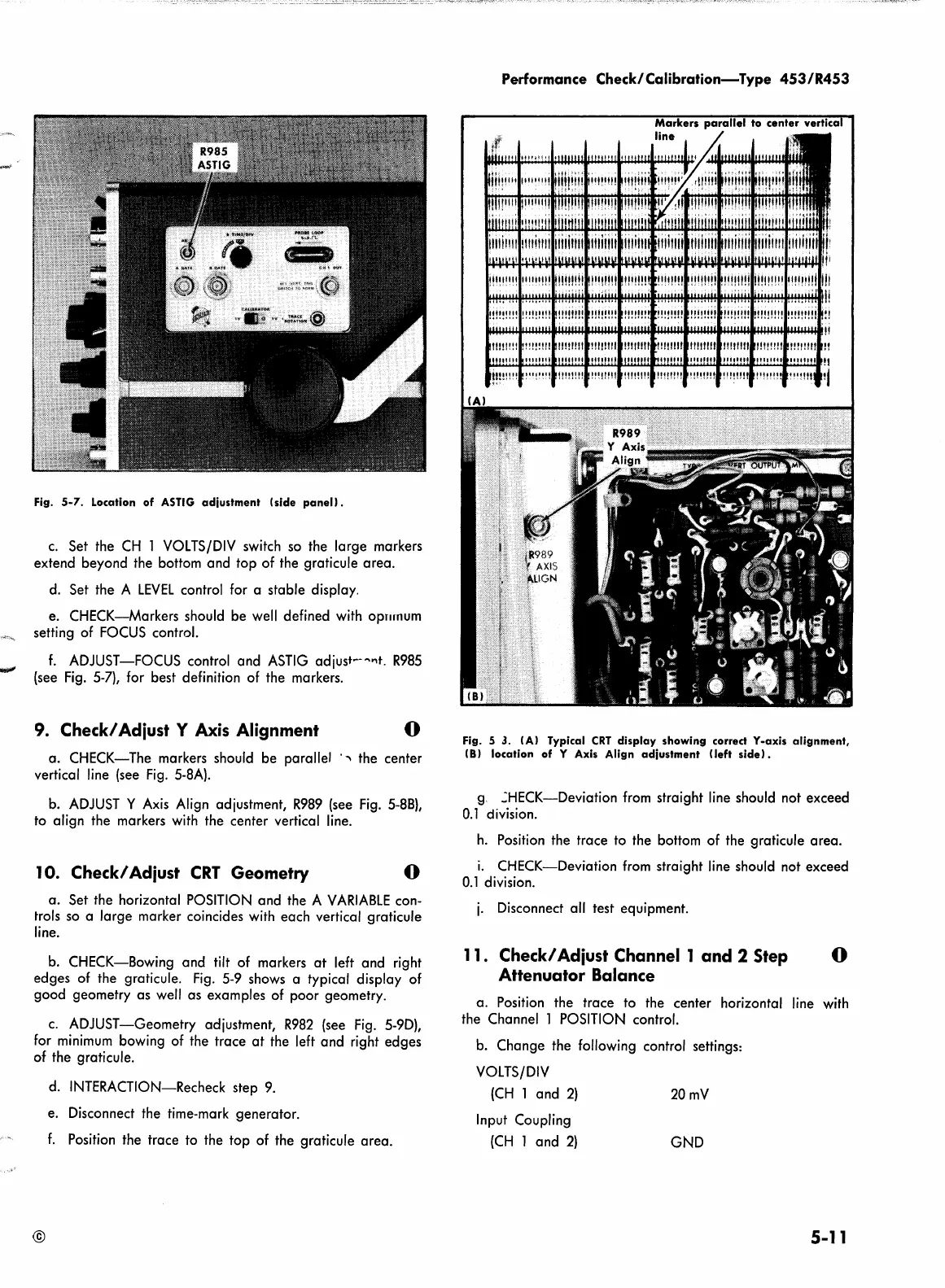
9. Check/ Adiust Y Axis Alignment
0
a. CHECK-The markers should be parallel ·
~
the center
vertical
line
(see
Fig.
5-8A).
b.
ADJUST
Y
Axis
Align
adjustment,
R989
(see
Fig.
5-8B),
to
align the markers
with
the center vertical
line.
10. Check/ Adiust
CRT
Geometry
0
a. Set the horizontal
POSITION
and the A
VARIABLE
con-
trols so a large marker coincides
with
each vertical graticule
line.
b.
CHECK-Bowing and tilt of markers
at
left and right
edges
of
the graticule.
Fig.
5-9
shows a typical display of
good geometry as
well
as examples of poor geometry.
c.
ADJUST-Geometry adjustment,
R982
(see
Fig.
5-9D),
for
minimum
bowing of the trace
at
the left and right edges
of
the graticule.
d.
INTERACTION-Recheck step
9.
e. Disconnect the time-mark generator.
f.
Position the trace to the top of the graticule area.
©
Performance
Check/Calibration-Type
453/R453
Markers
parallel
to
center
vertica
line
Fig. 5
3. IAI Typical
CRT
display
showing correct Y-axis
alignment,
(Bl location of Y Axis Align
adjustment
!left
side).
g.
.:HECK-Deviation
from
straight
line
should not exceed
0.1
division.
h.
Position the trace to the bottom of the graticule area.
i.
CHECK-Deviation
from
straight
line
should not exceed
0.1
division.
j.
Disconnect all test equipment.
11
. Check/ Adiust Channel 1
and
2 Step 0
Attenuator Balance
a. Position the trace to the center horizontal
line
with
the Channel 1
POSITION
control.
b.
Change the following control settings:
VOLTS/DIV
(CH
1 and
2)
Input Coupling
(CH
l and
2)
20mV
GND
5-11
 Loading...


