Observe the
following
precautions when soldering to
ceramic
terminal strips.
1.
Use
a
hot
iron
for
a short time.
Apply
only
enough
he·at
to make the solder
flow
freely.
2.
Maintain
a clean,
properly
tinned tip.
3.
Avoid
putting pressure on the ceramic terminal strip.
4.
Do not
attempt
to fill the terminal-strip notch
with
solder;
use
only
enough solder to cover the wires adequately.
5.
Clean the flux from the terminal strip
with
a flux-
remover solvent.
Metal
Terminals.
When
soldering metal terminals (e.g.,
switch
terminals, potentiometers, etc),
ordinary
60/40
solder
can be used.
Use
a soldering iron with a 40- to
75-watt
rating and a
1
/
8
-inch
wide
wedge-shaped tip.
Observe the
following
precautions when soldering metal
terminals:
1.
Apply
only
enough heat to make the solder
flow
freely.
2.
Apply
only
enough solder to form a solid connection.
Excess
solder may
impair
the function
of
the part.
3.
If
a
wire
extends beyond the solder joint, clip
off
the
excess.
4.
Clean the flux from the solder joint with a flux-remover
solvent.
Component Replacement
WARNING
Disconnect
the
instrument
from
the
power
source
before
replacing
components.
Removing the Rear Panel. The rear panel must be
removed
for
access to the rear subpanel. This panel can be
removed
by
removing the Z Axis ground strap and the four
screws located near the rear feet.
Swing-Out
Chassis.
Some
of
the controls and connectors
are mounted on a swing-out
chassis
on
the
right
side
of
this
instrument.
To
reach the rear
of
this chassis
or
the com-
ponents mounted behind it, first remove the top cover from
the instrument. Then, loosen the captive securing screw
so
the chassis can swing outward.
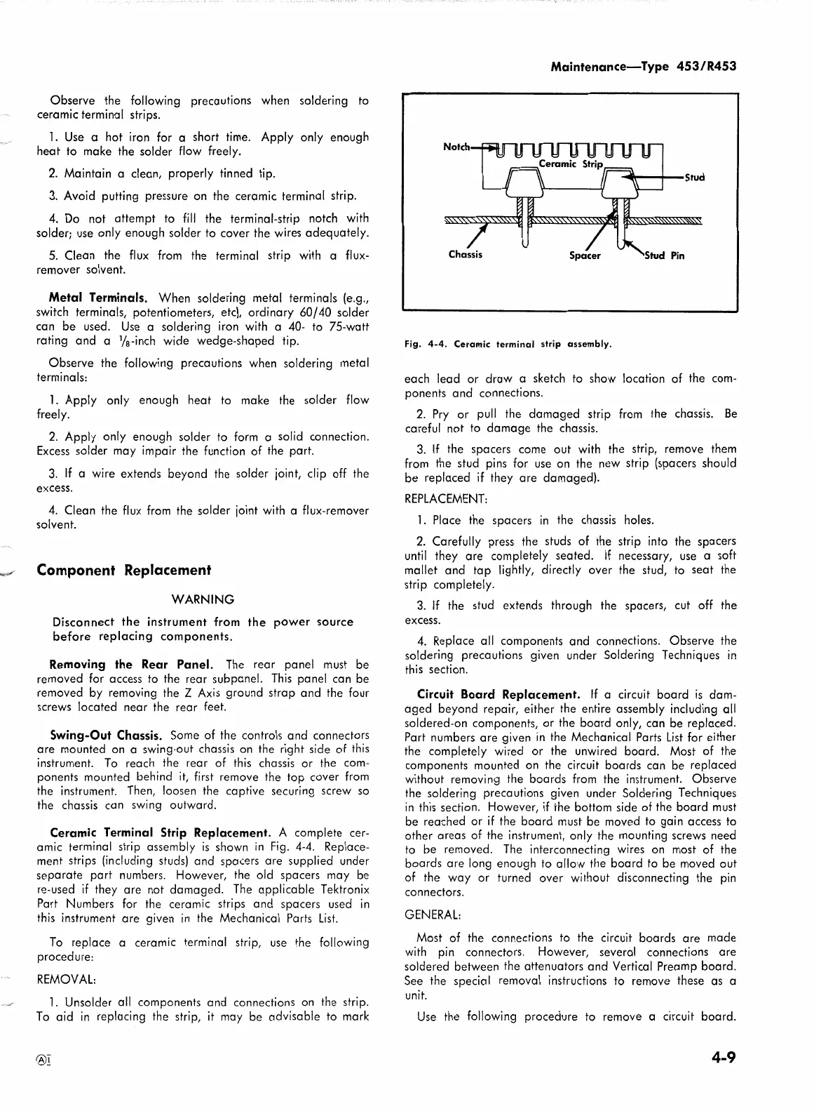
Ceramic Terminal Strip Replacement. A complete cer-
amic terminal strip assembly
is
shown in Fig. 4-4. Replace-
ment strips (including studs) and spacers are supplied under
separate
part
numbers. However, the old spacers may be
re-used
if
they are not damaged. The
applicable
Tektronix
Part Numbers
for
the ceramic strips and spacers
used
in
this instrument are given in the Mechanical
Parts
List.
To replace a ceramic terminal strip,
use
the
following
procedure:
REMOVAL:
1.
Unsolder
all
components and connections
on
the strip.
To
aid
in replacing the strip,
it
may be advisable to mark
®!
Maintenance-Type
453/R453
Fig.
4-4.
Ceramic
terminal
strip
assembly.
each lead
or
draw
a sketch to show location
of
the com-
ponents
and
connections.
2.
Pry
or
pull the
damaged
strip from the chassis.
Be
careful
not
to
damage
the
chassis.
3.
If
the spacers come
out
with
the strip, remove them
from the stud pins
for
use
on the new strip (spacers should
be replaced
if
they are damaged).
REPLACEMENT:
1.
Place the spacers in the chassis holes.
2.
Carefully
press
the studs
of
the strip into the spacers
until they are completely seated.
If
necessary,
use
a soft
mallet and
tap
lightly, directly over the stud, to seat the
strip
completely.
3.
If
the stud extends through the spacers, cut
off
the
excess.
4.
Replace
all
components and connections. Observe the
soldering precautions given under Soldering Techniques in
this section.
Circuit Board Replacement. If a circuit
board
is
dam-
aged
beyond repair, either the entire assembly including
all
soldered-on components,
or
the
board
only, can be replaced.
Part
numbers are given in the Mechanical Parts
List
for
either
the
completely
wired
or
the unwired board. Most
of
the
components mounted on the circuit boards can be replaced
without
removing the boards from the instrument. Observe
the
soldering precautions given under Soldering Techniques
in this section. However,
if
the bottom side
of
the board must
be reached
or
if
the
board
must be moved to gain access to
other areas
of
the instrument,
only
the mounting screws need
to be removed.
The
interconnecting wires on most
of
the
boards are
long enough to
allow
the
board
to be moved
out
of
the
way
or
turned over
without
disconnecting the pin
connectors.
GENERAL:
Most
of
the connections to the circuit boards are made
with pin connectors. However,
several connections are
soldered between the attenuators and Vertical Preamp
board.
See
the special removal instructions to remove these
as
a
unit.
Use
the
following
procedure to remove a circuit board.
4-9