Circuit
Description-Type
453/R453
From
Q63,
SW2308
!TRIGGER I
I
Ch
1 Vertical
---~r
Preamp
From
Q284,
Vertical
Switching
NORM
R402p
[;TI
R404
+150V
Internal
trigger
signal
to
A Trigger
Generator
Internal
trigger
signal
to
8 Trigger
Generator
L~
--8-4_0_0
_________
• 8401
§JJ
[fill
(A
Triggering I ( 8 Triggering I
_
CH
1 ONLY
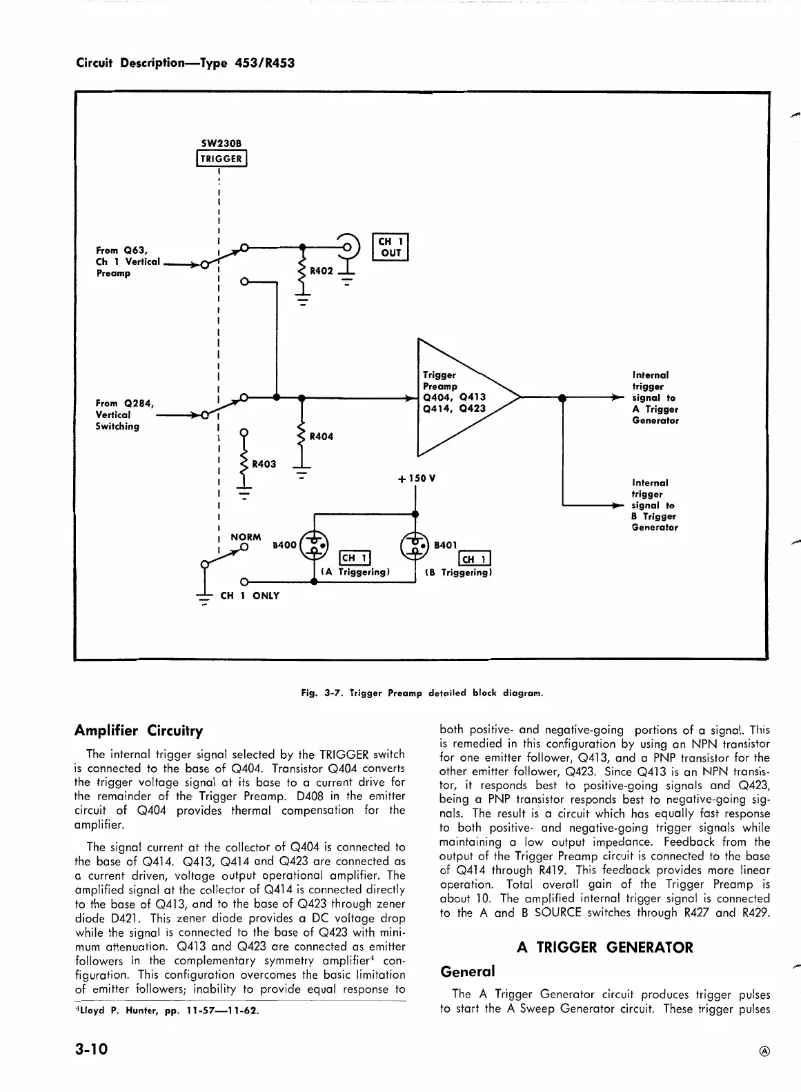
Fig.
3-7.
Trigger Preamp detailed block diagram.
Amplifier Circuitry
The
internal trigger signal selected by the
TRIGGER
switch
is
connected to the base of Q404. Transistor Q404 converts
the trigger voltage signal
at
its
base to a current drive for
the remainder of the Trigger Preamp. 0408
in
the emitter
circuit of Q404 provides thermal compensation for the
amplifier.
The
signal current
at
the collector of Q404
is
connected
to
the base of Q414. Q413, Q414
and
Q423
are
connected as
a current driven, voltage output operational amplifier.
The
amplified signal
at
the collector of Q414
is
connected directly
to the base of Q413, and to the base of Q423 through zener
diode 0421.
This
zener diode provides a
DC
voltage drop
while the signal
is
connected to the base of Q423 with
mini-
mum
attenuation. Q413 and Q423
are
connected as emitter
followers
in
the complementary symmetry amplifier
4
con-
figuration.
This
configuration overcomes the basic limitation
of emitter followers; inability to provide equal response
to
4
Lloyd
P.
Hunter, pp.
11-57-11-62.
3-10
both positive- and negative-going portions of a signal.
This
is
remedied
in
this
configuration by
using
an
NPN
transistor
for one emitter follower, Q413, and a
PNP
transistor for the
other emitter follower, Q423. Since Q413
is
an
NPN
transis-
tor,
it
responds best to positive-going signals and Q423,
being a
PNP
transistor responds best
to
negative-going sig-
nals.
The
result
is
a circuit which has equally fast response
to
both positive- and negative-going trigger signals while
maintaining a
low
output impedance. Feedback
from
the
output of the Trigger Preamp circuit
is
connected to the base
of Q414 through
R419.
This
feedback provides more linear
operation. Total overall gain of the Trigger Preamp
is
about
10.
The
amplified internal trigger signal
is
connected
to the A and B
SOURCE
switches through
R427
and
R429.
A
TRIGGER
GENERATOR
General
The
A Trigger Generator circuit produces trigger pulses
to start the A Sweep Generator circuit. These trigger pulses
®