-
SWEEP
TRlG'O
Fig.
2-9.
A AND B TIME/DIV switch.
Sweep
Magnification
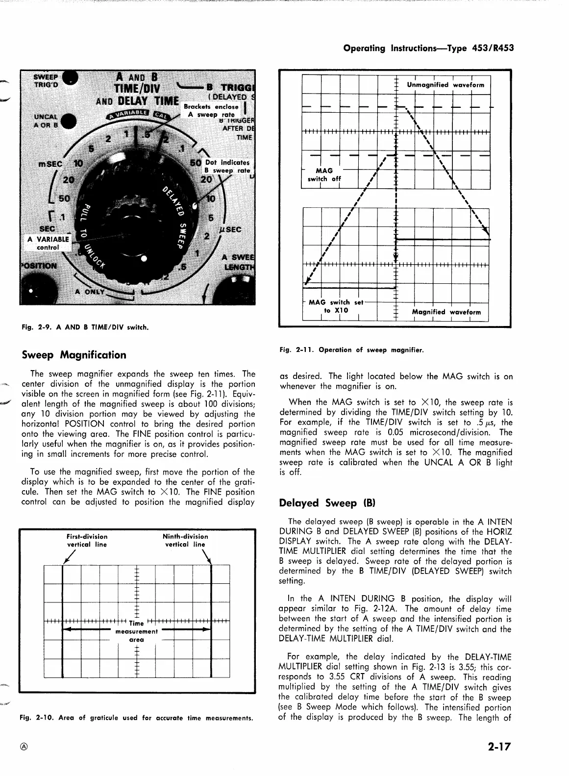
The
sweep magnifier expands the sweep ten times.
The
center division of the unmagnified display
is
the portion
visible on the screen
in
magnified
form
(see
Fig.
2-11
).
Equiv-
...,,,,,,,
a lent length of the magnified sweep
is
about 100 divisions;
any
10 division portion may be viewed
by
adjusting the
horizontal
POSITION
control to bring the desired portion
onto the viewing area.
The
FINE
position control
is
particu-
larly
useful
when the magnifier
is
on, as
it
provides position-
ing
in
small increments for more precise control.
To
use
the magnified sweep,
first
move the portion of the
display which
is
to
be expanded to the center of the grati-
cule.
Then
set the
MAG
switch to X 10.
The
FINE
position
control can be adjusted to position the magnified display
First-division
vertical line
/
I
-
....
Time
measurement
area
I-
-
I-
-
I-
I-
Ninth-division
vertical line
Fig.
2-10.
Area
of
graticule
used
for
accurate
time
measurements.
®
Operating Instructions-Type
453/R453
MAG
switch
off
/
1/
l
~'
,
,
-j
i
I
.
MAG switch
to XlO
I I
,
,
,
set
I
,
,
,
l
~
Unmagnified
waveform
'
'
'
~
'
'
'
..
"
Magnified
waveform
I I I I
Fig.
2-11.
Operation
of
sweep
magnifier.
as desired.
The
light located below the
MAG
switch
1s
on
whenever the magnifier
is
on.
When the
MAG
switch
is
set to X 10, the sweep rate
is
determined
by
dividing the
TIME/DIV
switch setting
by
10.
For
example,
if
the
TIME/DIV
switch
is
set to
.5
µs, the
magnified sweep rate
is
0.05 microsecond/division.
The
magnified sweep rate
must
be used for all
time
measure-
ments when the
MAG
switch
is
set to X 10.
The
magnified
sweep rate
is
calibrated when the
UNCAL
A
OR
B light
is
off.
Delayed Sweep
(8)
The
delayed sweep
(B
sweep)
is
operable
in
the A
INTEN
DURING
B and
DELAYED
SWEEP
(B)
positions of the
HORIZ
DISPLAY
switch.
The
A sweep rate along
with
the
DELAY-
TIME
MULTIPLIER
dial setting determines the
time
that the
B sweep
is
delayed. Sweep rate of the delayed portion
is
determined by the B
TIME/DIV
(DELAYED
SWEEP)
switch
setting.
In
the A
INTEN
DURING
B position, the display
will
appear
similar to
Fig.
2-12A.
The
amount of delay
time
between the start of A sweep and the intensified portion
is
determined
by
the setting of the A
TIME/DIV
switch and the
DELAY-TIME
MULTIPLIER
dial.
For
example, the delay indicated by the
DELAY-TIME
MULTIPLIER
dial setting shown
in
Fig.
2-13
is
3.55;
this
cor-
responds to 3.55
CRT
divisions of A sweep.
This
reading
multiplied
by
the setting of the A
TIME/DIV
switch gives
the calibrated delay
time
before the start of the B sweep
(see
B Sweep Mode which
follows).
The
intensified portion
of the display
is
produced
by
the B sweep.
The
length of
2-17