Circuit
Description-Type 453/R453
SW530A
B
ends
A
pulse from
B Sweep
Generator
A
SWEEP
~
__
----1
LENGTH
~
.
A
TIME/DIV
l-1
I
SW555
..........
..,.,,...
I B
ENDS
Al
....................
I
I
I
------
,
..........
,,
,....,,
,'
....................
Sweep
Reset
Multivibrator
---
---,
SW580
Q575,
Q585
I A
SWEEP
MODE I
SW569
,,
" :
.....
1
RESET
I
I
Auto
gate
from
Auto
Multi-
,,,,",,
.....
vibrator
8597
8596
I
REml
A
SWEEP
TRIG'D
Trigger
pulse
~------------11
...
from A Trigger
Generator
Sweep Gate
D505,
Q504
Disconnect
Diode
0533
/
/
Sawtooth Sweep
Generator
Q533,
Q531
/
/
I
/
A sweep to
Delay-Pickoff
Comparator
B Sweep
Generator
A sweep
to
Horizontal
Amplifier
A
VARIABLE
A
unblanking
gate
Alternate
trace
sync
pulse
~I
A GATE
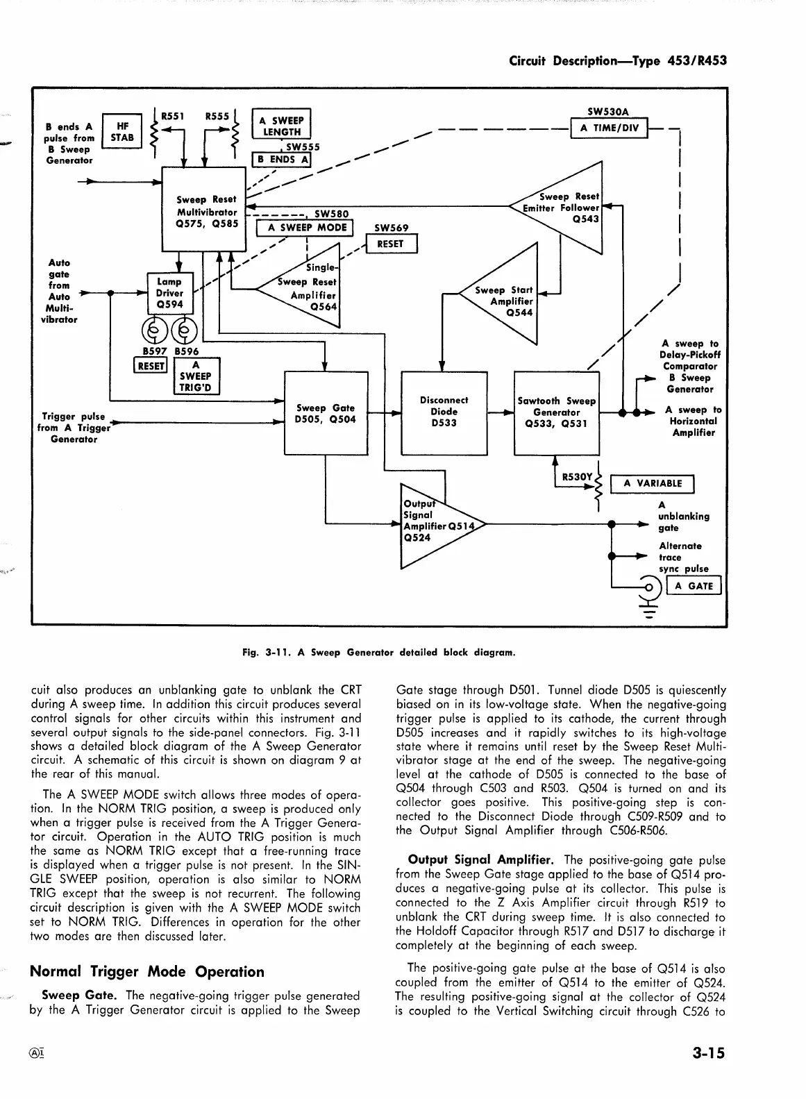
Fig.
3-11.
A Sweep Generator detailed block diagram.
cuit also produces an unblanking
gate
to unblank the
CRT
during A sweep time.
In
addition
this
circuit produces several
control signals for other circuits within
this
instrument and
several output signals to the side-panel connectors.
Fig.
3-11
shows a detailed block diagram of the A Sweep Generator
circuit. A schematic of
this
circuit
is
shown on diagram 9
at
the rear of
this
manual.
The
A
SWEEP
MODE
switch allows three modes of opera-
tion.
In
the
NORM
TRIG
position, a sweep
is
produced only
when a trigger pulse
is
received
from
the A Trigger Genera-
tor circuit. Operation
in
the
AUTO
TRIG
position
is
much
the same as
NORM
TRIG
except that a free-running trace
is
displayed when a trigger pulse
is
not present.
In
the
SIN-
GLE
SWEEP
position, operation
is
also similar to
NORM
TRIG
except that the sweep
is
not recurrent.
The
following
circuit description
is
given with the A
SWEEP
MODE
switch
set
to
NORM
TRIG.
Differences
in
operation for the other
two modes are then discussed later.
Normal Trigger Mode Operation
Sweep
Gate.
The
negative-going trigger pulse generated
by the A Trigger Generator circuit
is
applied to the Sweep
®!
Gate
stage through
DSOl.
Tunnel
diode
DSOS
is
quiescently
biased on
in
its
low-voltage state. When the negative-going
trigger pulse
is
applied to
its
cathode, the current through
DSOS
increases and
it
rapidly switches
to
its
high-voltage
state where
it
remains
until
reset by the Sweep
Reset
Multi-
vibrator stage
at
the end of the sweep.
The
negative-going
level
at
the cathode of
DSOS
is
connected
to
the base of
QS04 through
C503
and
R503.
Q504
is
turned
on
and
its
collector goes positive.
This
positive-going step
is
con-
nected to the Disconnect Diode through
C509-R509
and
to
the Output Signal Amplifier through
C506-R506.
Output Signal Amplifier.
The
positive-going
gate
pulse
from
the Sweep
Gate
stage applied to the base of QSl 4 pro-
duces a negative-going pulse
at
its
collector.
This
pulse
is
connected to the Z
Axis
Amplifier circuit through
RSl
9 to
unblank the
CRT
during sweep time.
It
is
also connected to
the Holdoff Capacitor through
RSl
7 and
DSl
7 to discharge·
it
completely
at
the beginning of each sweep.
The
positive-going
gate
pulse
at
the base of QSl 4
is
also
coupled
from
the emitter of QSl 4 to the emitter of QS24.
The
resulting positive-going signal
at
the collector of QS24
is
coupled to the Vertical Switching circuit through
C526
to
3-15