-1950
v
3~Vl10A
H~tH
~
3
~N'tffl
R940
CRT
Grid
Bias
····~
Performance Check/Calibration-Type
453/R453
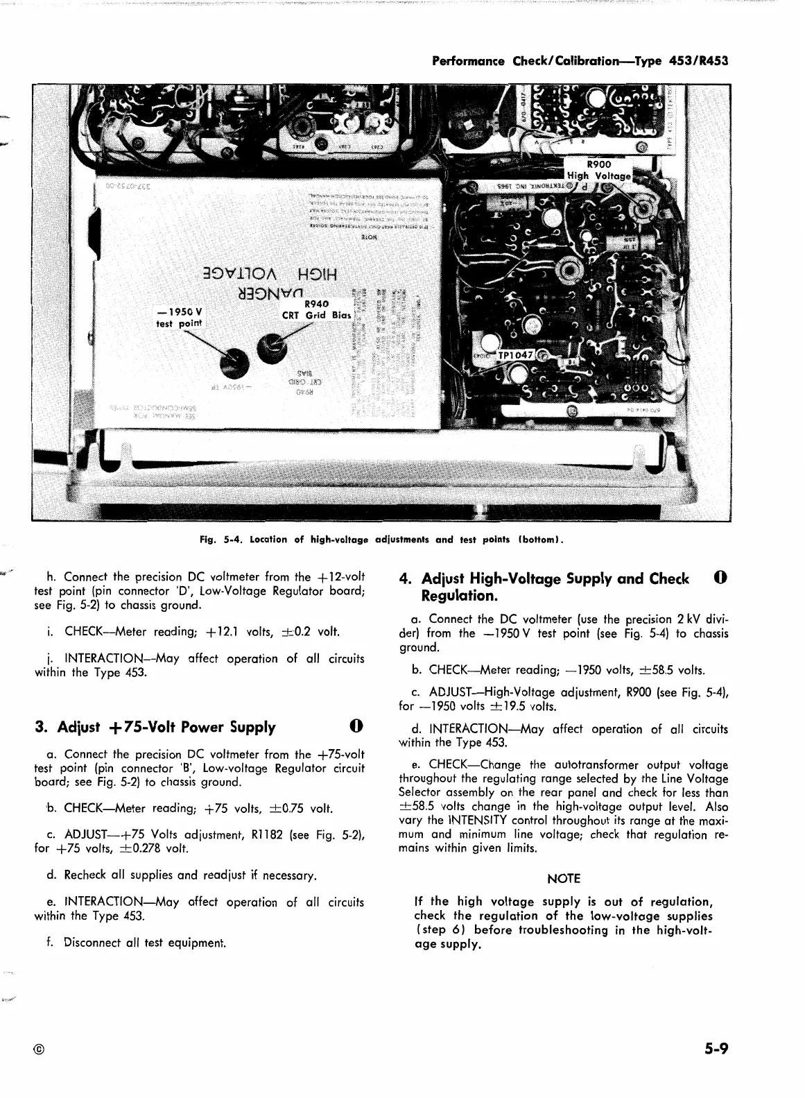
Fig.
5-4.
Location
of
high-voltage
adjustments
and
test points I
bottom).
h.
Connect the precision
DC
voltmeter from the + 12-volt
test point (pin connector 'D', Low-Voltage Regulator
board;
see Fig. 5-2) to chassis ground.
i.
CHECK-Meter
reading; +
12.1
volts,
+0.2
volt.
j.
INTERACTION-May affect
operation
of all circuits
within the Type 453.
3. Adiust + 75-Volt Power Supply 0
a.
Connect the precision
DC
voltmeter from the
+75-volt
test point (pin connector 'B', Low-voltage Regulator circuit
board;
see
Fig. 5-2) to chassis ground.
h.
CHECK-Meter
reading;
+75
volts,
+0.75
volt.
c.
ADJUST-+75
Volts adjustment,
Rl
182 (see
Fig.
5-2),
for
+75
volts,
+0.278
volt.
d. Recheck all supplies
and
readjust
if
necessary.
e. INTERACTION-May affect
operation
of all circuits
within the Type 453.
f.
Disconnect all test equipment.
©
4. Adiust High-Voltage Supply and
Check
Regulation.
0
a.
Connect the
DC
voltmeter (use the precision 2
kV
divi-
der) from
the
-1950
V test point (see Fig. 5-4) to chassis
ground.
b.
CHECK-Meter
reading;
-1950
volts,
+58.5
volts.
c.
ADJUST-High-Voltage
adjustment,
R900
(see Fig. 5-4),
for
-1950
volts + 19.5 volts.
d.
INTERACTION-May affect
operation
of all circuits
within the Type 453.
e.
CHECK-Change
the autotransformer output
voltage
throughout the regulating
range
selected by the
Line
Voltage
Selector assembly on the
rear
panel
and
check for less than
+58.5
volts
change
in
the high-voltage
output
level. Also
vary the
INTENSITY
control throughout
its
range
at
the maxi-
mum
and
minimum line voltage; check
that
regulation re-
mains within given limits.
NOTE
If
the
high
voltage
supply
is
out
of
regulation,
check
the
regulation
of
the
low-voltage
supplies
{step
6)
before
troubleshooting
in
the
high-volt-
age
supply.
5-9
 Loading...


