The
circuit boards are also outlined on the diagrams
with
a
blue
line.
These pictures, used along with the diagrams, aid
in
locating the components mounted on the circuit boards.
Wiring Color-Code.
All
insulated wire and cable used
in
the Type
453
is
color-coded to facilitate circuit tracing.
Signal carrying leads are identified with one or two colored
stripes. Voltage supply leads
are
identified with three stripes
to indicate the approximate voltage
using
the
EIA
resistor
color code. A white background color indicates a positive
voltage and a tan background indicates a negative voltage.
The
widest color stripe identifies the
first
color of the
code·.
Table
4-2
gives the wiring color-code for the power-supply
voltages used
in
the Type
453.
TABLE
4-2
Power Supply Wiring Color
Code
Back-
Supply
ground
First Second
Third
Color
Stripe Stripe Stripe
-12
volt
Tan
Brown
Red
Black
+
12
volt
White
Brown
Red
Black
+75
volt
White
Viole·t
Green
Black
+
150
volt
White
Brown
Green
Brown
Metal-Film Resistors:
Ceramic Capacitors:
0@
and
0
-1st,
2nd
and
3rd
significant figures;
@
-multiplier;
©
-tolerance;
Maintenance-Type
453/R453
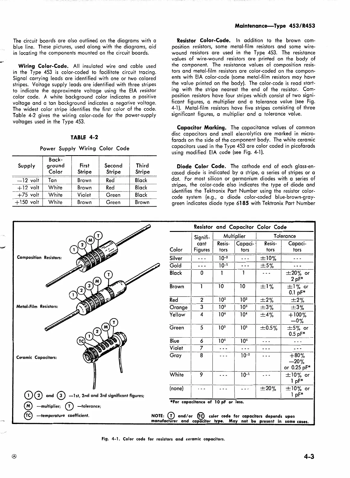
Resistor Color-Code.
In
addition to the brown
com-
position resistors, some metal-film resistors and some wire-
wound resistors
are
used
in
the Type
453.
The
resistance
values of wire-wound resistors are printed
on
the body of
the component.
The
resistance values of composition
resis-
tors and metal-film resistors
are
color-coded
on
the compon-
ents with
EIA
color-code
(some
metal-film resistors may have
the value printed on the body).
The
color-code
is
read start-
ing
with
the stripe nearest the end of the resistor.
Com-
position resistors have four stripes which consist of two signi-
ficant figures, a multiplier and a tolerance value
(se·e
Fig.
4-1
).
Metal-film resistors have
five
stripes consisting of three
significant figures, a multiplier and a tolerance value.
Capacitor
Marking. The capacitance values of common
disc capacitors and small elecrolytics
are
marked
in
micro-
farads
on
the side of the component body.
The
white ceramic
capacitors used
in
the Type
453
are
color coded
in
picofarads
using
modified
EIA
code (see
Fig.
4-1}.
Diode Color
Code.
The
cathode end of each glass-en-
cased diode
is
indicated by a stripe, a series of stripes or a
dot.
For
most silicon or germanium diodes
with
a series of
stripes, the color-code also indicates the type of diode and
identifies the Tektronix Part Number
using
the resistor color-
code system (e.g., a diode color-coded blue-brown-gray-
green indicates diode type
6185
with
Tektronix Part Number
Resistor
and
Capacitor Color Code
Signifi- I Multiplier Tolerance
.cant
I
Resis-
I Capaci-1
Resis-
Capaci-
Color
F1gures
___!_~
tors tors tors
Silver
I
10-
2
Gold I
10-1
Black
I 0
+10%
+5%
+20%
or
2 pf*
Brown
I
+l
% or
0.1
pf*
~l:~-2~~~1-0-
2
--+~10-
2
~1--+-2-~-o-~,~+-'-2-%~-•
10
+1%
10
Orange I 3
10
3
10
3
+3%
I
+3%
Yellow I 4
10
4
.,___l-0
4
_1._~4%
..
I __ + ___
1~_~/:_10_.
Green I 5
10
5
Blue
I 6
106
Violet I 7
Gray
White
I 9
(none)
I
10
5
+0.5%
lQ6
10-2
+5%
or
0.5
pf*
+80%
-20%
or
0.25
pf*
10-
1
~--
+10%
or
1 pf*
!-=-=-
+20%
1
-+-1---'o-~-o
-o-r
-•
I 1
pF*
*For
capacitance
of
10
pf
or
less.
@
-temperature
coefficient.
NOTE:
(!)
and/or
@.
color
code
for capacitors
depends
upon
manufacturer
and
capacitor
type.
May
not
be
present
in some cases.
Fig.
4-1.
Color
code
for resistors
and
ceramic capacitors.
®
4-3
 Loading...


