Performance Check/Calibration-Type
453/R453
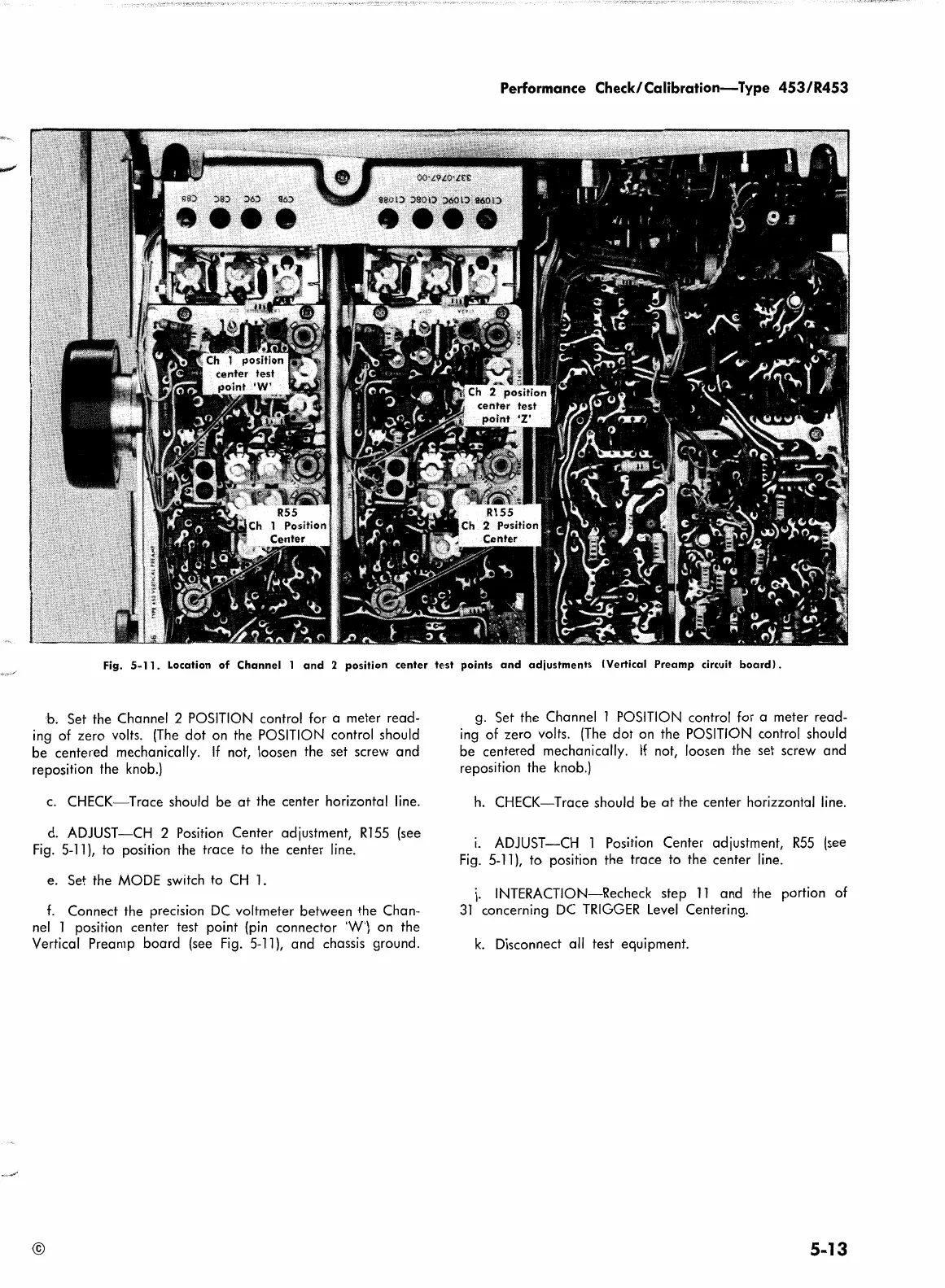
Fig.
5-11.
Location
of
Channel
l
and
2
position
center
tf~st
points
and
adjustments
!Vertical
Preamp
circuit
board).
b. Set the Channel 2
POSITION
control for a meter read-
ing
of zero volts.
(The
dot
on
the
POSITION
control should
be centered mechanically.
If
not, loosen the set screw and
reposition the
knob.}
c.
CHECK-Trace should be
at
the center horizontal
line.
d.
ADJUST-CH 2 Position Center adjustment,
Rl
55
(see
Fig.
5-11
},
to position the trace to the center line.
e. Set the
MODE
switch to
CH
1.
f.
Connect the precision
DC
voltmeter between the Chan-
nel
l position center test point
(pin
connector
'W'}
on
the
Vertical Preamp board (see
Fig.
5-11
},
and chassis ground.
©
g.
Set the Channel l
POSITION
control for a meter read-
ing
of zero volts.
(The
dot
on
the
POSITION
control should
be centered mechanically.
If
not, loosen the set screw and
reposition the
knob.}
h.
CHECK-Trace should be
at
the center horizzontal
line.
1.
ADJUST-CH 1 Position Center adjustment,
R55
(see
Fig.
5-11},
to position the trace to the center line.
j.
INTERACTION-Recheck step
11
and the portion of
31
concerning
DC
TRIGGER
Level
Centering.
k.
Disconnect all test equipment.
5-13
 Loading...


