D
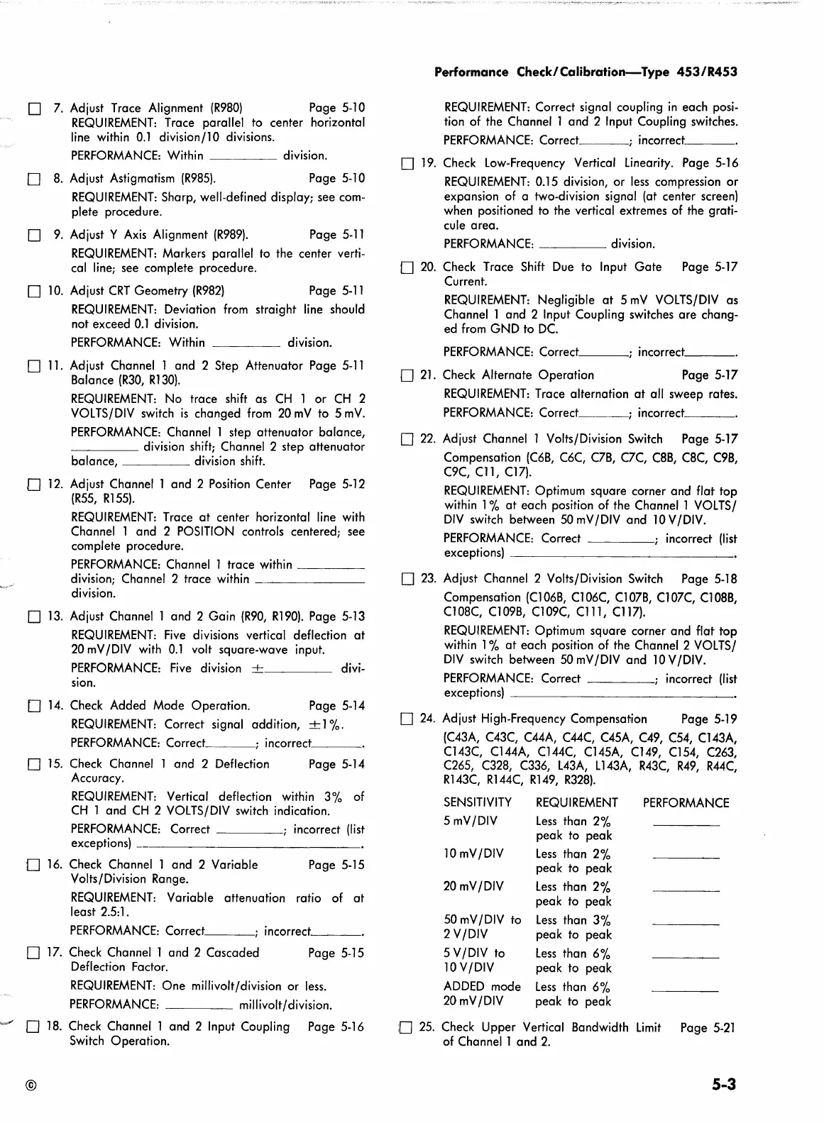
7.
Adjust Trace Alignment
(R980)
Page
5-10
REQUIREMENT:
Trace parallel to center horizontal
line
within
0.1
division
fl
0 divisions.
PERFORMANCE:
Within division.
D
8.
Adjust Astigmatism
(R985).
Page
5-10
REQUIREMENT:
Sharp, well-defined display; see
com-
plete procedure.
D
9.
Adjust Y
Axis
Alignment
(R989).
Page
5-11
REQUIREMENT:
Markers parallel
to
the center verti-
cal
line;
see complete procedure.
0
10.
Adjust
CRT
Geometry
(R982)
Page
5-11
REQUIREMENT:
Deviation
from
straight
line
should
not exceed
0.1
division.
PERFORMANCE:
Within
division.
D
11.
Adjust Channel l and 2 Step Attenuator Page
5-11
Balance
(R30,
Rl
30).
REQUIREMENT:
No
trace
shift
as
CH
1 or
CH
2
VOLTS/DIV
switch
is
changed
from
20mV to SmV.
PERFORMANCE:
Channel l step attenuator balance,
____
division
shift;
Channel 2 step attenuator
balance, division
shift.
0
12.
Adjust Channel 1 and 2
Position
Center Page
5-12
(R55,
Rl
55).
REQUIREMENT:
Trace
at
center horizontal
line
with
Channel 1 and 2
POSITION
controls centered; see
complete procedure.
PERFORMANCE:
Channel l trace within
___
_
division; Channel 2 trace
within-~----
division.
D
13.
Adjust Channel 1 and 2 Gain
(R90,
Rl90).
Page
5-13
REQUIREMENT:
Five
divisions vertical deflection
at
20
mV
/DIV
with
0.1
volt square-wave input.
PERFORMANCE:
Five
division
-+-
divi-
sion.
D
14.
Check Added Mode Operation.
Page
5-14
REQUIREMENT:
Correct signal addition,
-+-1
%.
PERFORMANCE:
Correct ; incorrect
___
,
D
15.
Check
Channel 1 and 2 Deflection
Page
5-14
Accuracy.
REQUIREMENT:
Vertical deflection within 3% of
CH
1 and
CH
2
VOLTS/DIV
switch
indication.
PERFORMANCE:
Correct incorrect
(list
exceptions)
0
16.
Check Channel 1 and 2 Variable Page
5-15
Volts/Division Range.
REQUIREMENT:
Variable attenuation ratio of
at
least
2.5:
1.
PERFORMANCE:
Correct ;
incorrect,
__
_
D
17.
Check Channel l and 2 Cascaded Page
5-15
Deflection Factor.
REQUIREMENT:
One millivolt/division or
less.
PERFORMANCE:
millivolt/division.
D
18.
Check
Channel l and 2 Input Coupling Page
5-16
Switch
Operation.
©
Performance Check/Calibration-Type
453/R453
REQUIREMENT:
Correct signal coupling
in
each
posi-
tion of the Channel l and 2 Input Coupling switches.
PERFORMANCE:
Correct ; incorrect
__
_
D
19.
Check Low-Frequency Vertical
Linearity.
Page
5-16
REQUIREMENT:
0.15
division, or
less
compression or
expansion of a two-division signal (at center screen)
when positioned to the vertical extremes
of
the grati-
cule area.
PERFORMANCE:
____
division.
O
20.
Check Trace
Shift
Due
to Input Gate Page
5-17
Current.
REQUIREMENT:
Negligible
at
5
mV
VOLTS/DIV
as
Channel 1 and 2 Input Coupling switches are chang-
ed
from
GND to
DC.
PERFORMANCE:
Correct
___
; incorrect
__
_
0
21.
Check Alternate Operation
Page 5-17
REQUIREMENT:
Trace alternation
at
all sweep rates.
PERFORMANCE:
Correct
___
; incorrect
__
_
D
22.
Adjust Channel 1 Volts/Division
Switch
Page 5-17
Compensation
(C6B,
C6C,
C7B,
C7C,
C8B,
CBC,
C9B,
C9C,
Cll,
Cl7).
REQUIREMENT:
Optimum square corner and flat top
within
1 %
at
each position of the Channel 1
VOLTS/
DIV
switch
between
50
mV
/DIV
and
10
V
/DIV.
PERFORMANCE:
Correct
----i
incorrect
(list
exceptions)
--------------
D
23.
Adjust Channel 2 Volts/Division
Switch
Page
5-18
Compensation
(Cl
06B,
Cl
06C,
Cl
07B,
Cl
07C,
Cl
08B,
Cl
08C,
Cl
09B,
Cl
09C,
Cl
11,
Cl
17).
REQUIREMENT:
Optimum square corner and flat top
within
1 %
at
each position
of
the Channel 2
VOLTS/
DIV
switch
between
50
mV
/DIV
and
10
V
/DIV.
PERFORMANCE:
Correct
___
_
incorrect
(list
exceptions)
-------------~
D
24.
Adjust High-Frequency Compensation Page
5-19
(C43A,
C43C,
C44A,
C44C,
C45A,
C49, C54,
Cl
43A,
Cl
43C,
Cl
44A,
Cl
44C,
Cl
45A,
Cl
49,
Cl
54,
C263,
C265, C328,
C336,
L43A,
L
143A,
R43C,
R49,
R44C,
Rl
43C,
Rl
44C,
Rl
49,
R328).
SENSITIVITY
REQUIREMENT
PERFORMANCE
5
mV/DIV
Less
than 2%
peak
to
peak
lOmV/DIV
Less
than 2%
peak
to
peak
20
mV/DIV
Less
than 2%
peak to peak
50
mV
/DIV
to
Less
than 3%
2
V/DIV
peak to peak
5
V/DIV
to
Less
than 6%
10
V
/DIV
peak to peak
ADDED
mode
Less
than 6%
20
mV
/DIV
peak to peak
:D
25.
Check Upper Vertical Bandwidth
Limit
Page
5-21
of
Channel 1 and
2.
5-3
 Loading...


