Appendix A: Specifications
A–6
TDS 340A, TDS 360 & TDS 380 User Manual
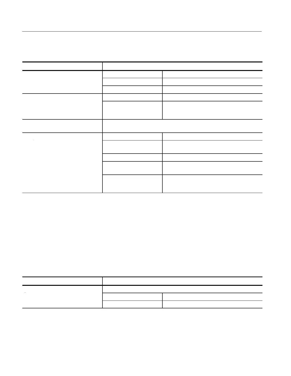
Table A–7: Typical characteristics — triggering system
Name Description
E
T
gg
n
Edg
T
gg
ng Acquire mode Trigger-position error
1,2
Sample, Average ±(1 WI + 2 ns)
Peak Detect, Envelope ±(2 WI + 2 ns)
n
y
V
d
Typ
T
gg
Source Typical sensitivity
CH1 or CH2
External
External/10
0.6 division of video sync signal
75 mV of video sync signal
750 mV of video sync signal
Lowest Frequency for Successful Operation
of “Set Level to 50%” Function
50 Hz
n
y
Edg
Typ
T
gg
DC
Trigger coupling Typical signal level for stable triggering
C
up
d
AC Same as DC-coupled limits
4
for frequencies above
60 Hz. Attenuates signals below 60 Hz.
Noise Reject Three and one half times the DC-coupled limits.
4
High Frequency Reject One and one half times times the DC-coupled limits
4
from DC to 30 kHz. Attenuates signals above 30 kHz.
Low Frequency Reject One and one half times the DC-coupled limits
4
for
frequencies above 80 kHz. Attenuates signals below
80 kHz.
1
The trigger position errors are typically less than the values given here. These values are for triggering signals having a
slew rate at the trigger point of ±0.5 division/ns.
2
The waveform interval (WI) is the time between the samples in the waveform record. Also, see the footnote for the
characteristics Sample Rate Range and Equivalent Time or Interpolated Waveform Rates in Table A–11 on page A–8.
3
The minimum sensitivity for obtaining a stable trigger. A stable trigger results in a uniform, regular display triggered on
the selected slope. The trigger point must not switch between opposite slopes on the waveform, and the display must not
“roll” across the screen on successive acquisitions. The TRIG’D LED stays constantly lighted when the SEC/DIV setting
is 2 ms or faster but may flash when the SEC/DIV setting is 10 ms or slower.
4
See the characteristic Sensitivity, Edge-Type Trigger, DC Coupled in Table A–3, which begins on page A–3.
Table A–8: Typical characteristics — probe compensator output
Name Description
u
pu
V
ag
and
qu
n
y
Characteristic
b
C
p
n
a
Voltage 5.0 V (low-high) into a 1 MW load
Frequency 1 kHz

 Loading...


