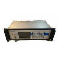
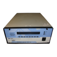
Model 400E Ozone Analyzer
Instruction Manual
Operating Instructions
P/N 04316 Rev: B 103
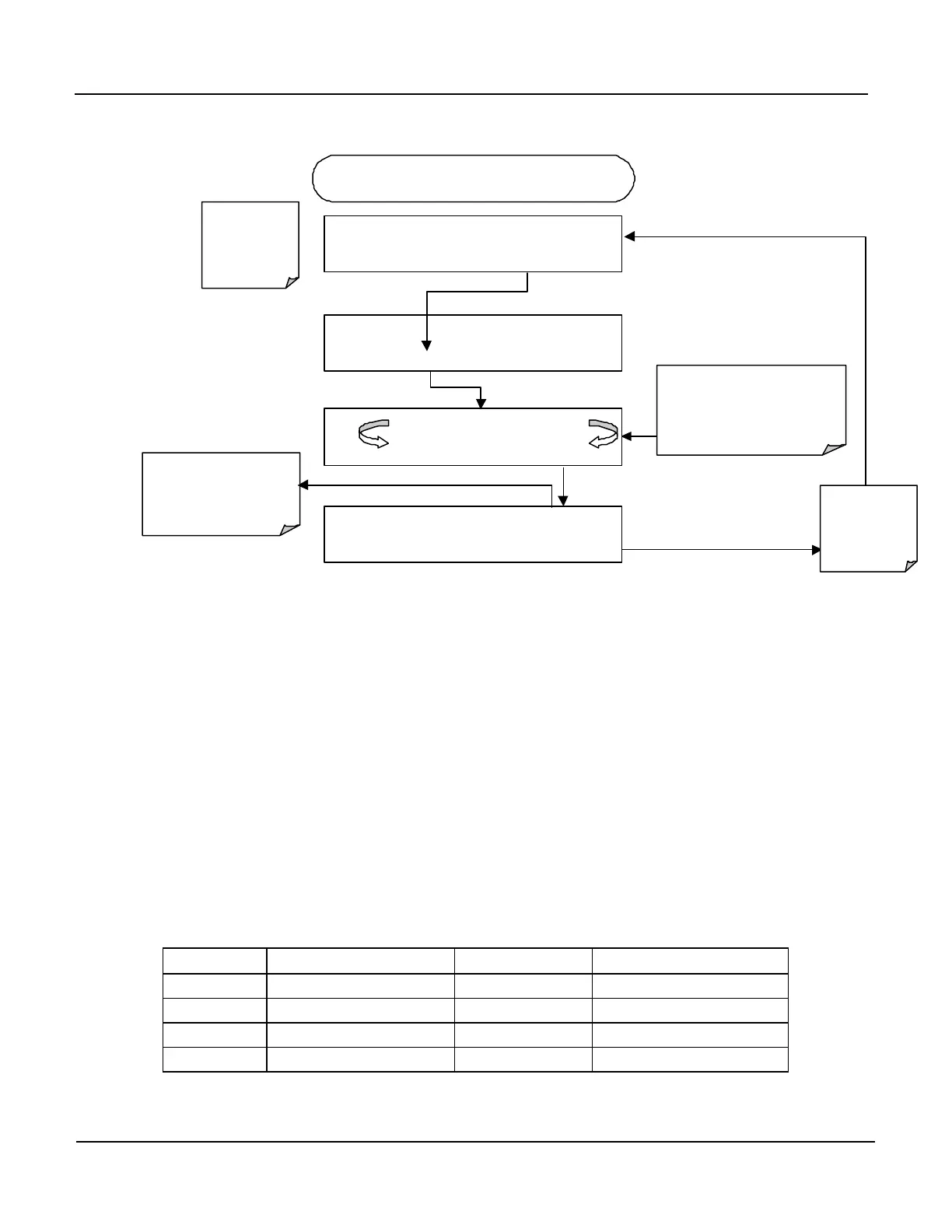
To calibrate the outputs as a group press the following:
DIAG AIO AUTO CALIBRATING CONC_OUT_1
AUTO CALIBRATING CONC_OUT_2
AUTO CALIBRATING TEST_OUTPUT
Exit at Any
to the main
DIAG Menu
DIAG
ANALOG I / O CONFIGURATION
PREV NEXT ENTR EXIT
DIAG AIO AOUTS CALIBRATED: NO
< SET SET> CAL EXIT
If AutoCal has been turned off for
any channel (see Section 6.7.3.5),
the message for that channel will
be similar to:
NOT AUTO CAL CONC_OUT_1
Exit to Return
to the I/O
Configuration
Menu
STARTING FROM DIAGNOSTIC MENU
If any of the channels have
not been calibrated this
message will read
NO
.
DIAG AIO AOUTS CALIBRATED:
< SET
SET> CAL
EXIT
6.7.3.5. Manually Calibrating Analog Output Signal Levels
The analog outputs in voltage mode can be manually calibrated to closely match
the characteristics of the data recorder. Outputs configured for 0.1V full scale
should ALWAYS be calibrated manually.
Calibration is done through the instrument software in conjunction with a voltmeter
connected across the output terminals (see Figure 6-2). Adjustments are made
using the front panel keys. First the zero-point is set then the span-point
(Table 6-12).
The software allows this adjustment to be made in 100, 10 or 1 count increments.
Table 6-12: Span Voltages and Adjustment Tolerances for Analog Output
Signal Calibration
Full Scale
Adjust Zero Within
Span Voltage Adjust Span Within
0.1 VDC ±0.0005V 90 mV ±0.001V
1 VDC ±0.001V 900 mV ±0.001V
5 VDC ±0.002V 4500 mV ±0.003V
10 VDC ±0.004V 4500 mV ±0.006V


 To Next Page