Model 400E Ozone Analyzer
Instruction Manual
Operating Instructions
P/N 04316 Rev: B 113
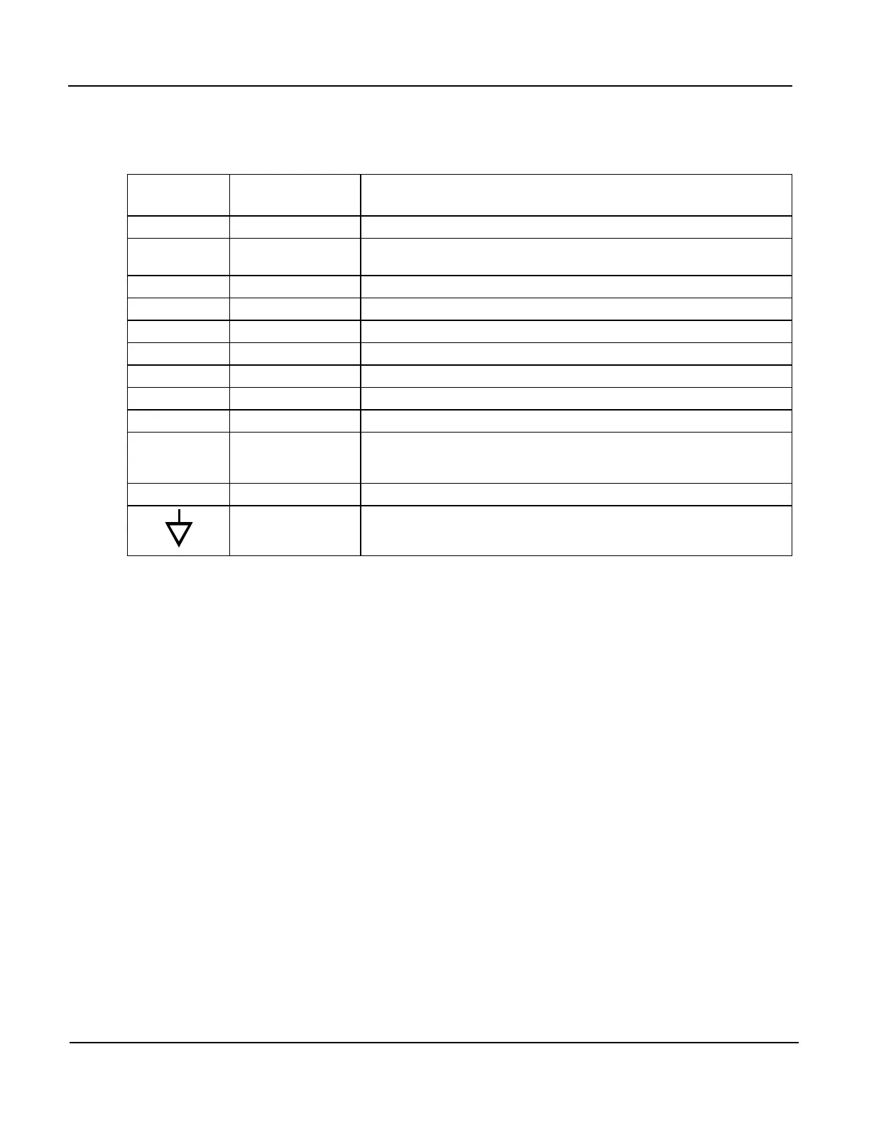
The pin assignments for the Status Outputs are:
Table 6-14: Status Output Pin Assignments
Rear Panel
Label
Status
Definition
Condition
1 SYSTEM OK On if no faults are present.
2 CONC VALID
On if O3 concentration measurement is valid.
If the O3 concentration measurement is invalid, this bit is OFF.
3 HIGH RANGE On if unit is in high range of DUAL or AUTO Range Modes
4 ZERO CAL On whenever the instruments ZERO point is being calibrated.
5 SPAN CAL On whenever the instruments SPAN point is being calibrated.
6 DIAG MODE On whenever the instrument is in DIAGNOSTIC mode.
7 SPARE
8 SPARE
D EMITTER BUSS The emitters of the transistors on pins 1-8 are bussed together.
SPARE
+ DC POWER + 5 VDC
Digital Ground
The ground level from the analyzer’s internal DC Power
Supplies.
6.8.2. Control Inputs
Several Control Inputs that allow the user to remotely initiate ZERO and SPAN
Calibration Modes are provided via an 10-pin connector labeled CONTROL IN on the
analyzer’s rear panel. These are opto-isolated digital inputs that are activated when
a 5 VDC signal is applied to the “U” pin.


 To Next Page