Getting Started Model 400E Ozone Analyzer
Instruction Manual
42 P/N 04316 Rev: B
NOTE
Once you have completed the above set-up procedures, please
fill out the Quality Questionnaire that was shipped with your
unit and return it to T-API.
This information is vital to our efforts in continuously improving
our service and our products.
THANK YOU.
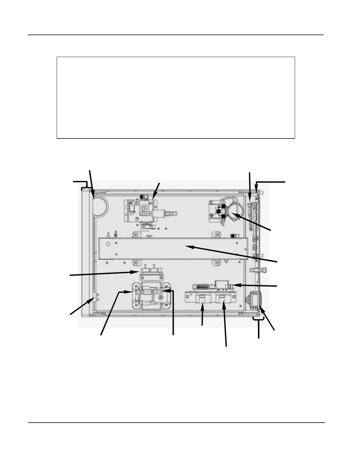
Particulate Filter
PS1
(+5 VDC; ±15VDC)
PS2
(+12 VDC)
Pump Assy
IZS
Option
Optical
Bench
Critical Flow
Orifice
Rear Panel
Mother
Board
Power
Receptacle
Measure /
Reference
Valve
Figure 3-5: Assembly Layout


 To Next Page