Model 400E Ozone Analyzer
Instruction Manual
Operating Instructions
P/N 04316 Rev: B 83
In its standard configuration the analyzer Analog Outputs can be set for the
following DC voltage signal levels. Each range has is usable from -5% to + 5% of
the rated span voltage.
Table 6-7: Analog Output Voltage Range Min/Max
Range Span Minimum Output Maximum Output
0-100 mVDC -5 mVDC 105 mVDC
0-1 VDC -0.05 VDC 1.05 VDC
0-5 VDC -0.25 VDC 5.25 VDC
0-10 VDC -0.5 VDC 10.5 VDC
The default offset for all ranges is 0 VDC.
The following DC Current output options are also available from the factory:
Table 6-8: Analog Output Current Loop Min/Max
RANGE MINIMUM OUTPUT
MAXIMUM OUTPUT
0-20 mA 0 mA 20 mA
These are the physical limits of the current loop modules, typical applications use 2-
20 or 4-20 mA for the lower and upper limits. Please specify desired range when
ordering this option.
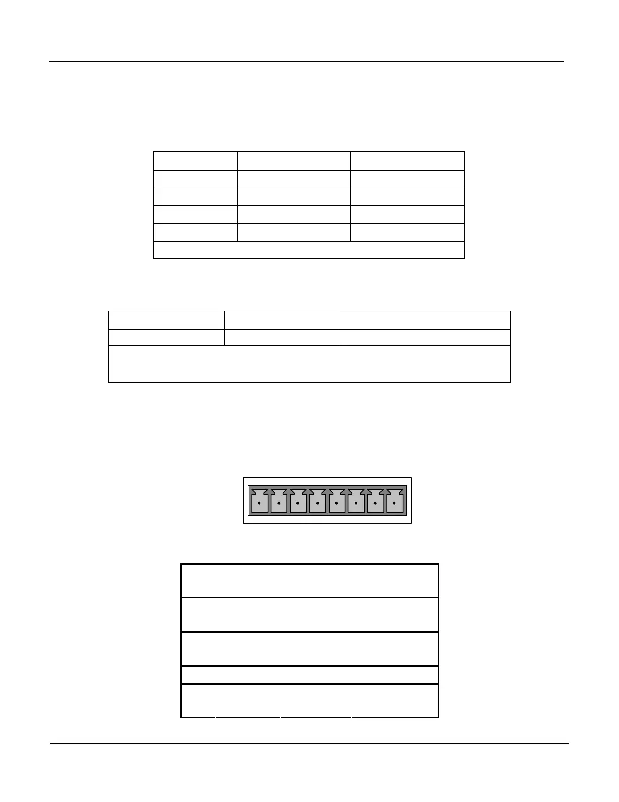
Pin assignments for the output connector at the rear panel of the instrument are
shown in Table 6-9.
ANALOG OUT
A1 A2 A3 A4
+ - + - + - + -
Table 6-9: Analog Output Pin Assignments
Pin
ANALOG
OUTPUT
VOLTAGE
SIGNAL
CURRENT
SIGNAL
1 V Out I Out +
2
A1
Ground I Out -
3 V Out I Out +
4
A2
Ground I Out -
5 A3 Not Used Not Used
7 V Out not available
8
A4
Ground not available