Getting Started Model 400E Ozone Analyzer
Instruction Manual
32 P/N 04316 Rev: B
NOTE
Sample Gas pressure must equal ambient atmospheric
pressure.
In applications where the sample gas is received from a
pressurized manifold, a vent must be placed as shown to
equalize the sample gas with ambient atmospheric pressure
before it enters the analyzer.
This vent line must be:
q At least 0.2m long
q No more than 2m long
q Vented outside the shelter or immediate
area surrounding the instrument
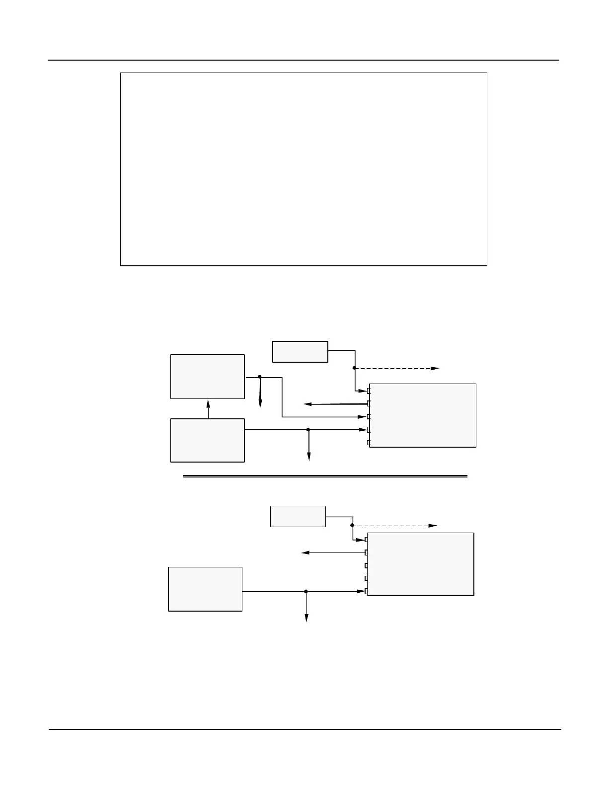
If your analyzer is equiped with wither the Zero/Span Valve Option (Option 50) or
the Internal Zero/Span Option (IZS - Option 51), the pneumatic connections should
be made as follows:
MODEL
400E
Sample
Dry Air
Exhaust
Span
Zero Air
VENT
MODEL 701
Zero Air Generator
Source of
SAMPLE Gas
VENT if input is pressurized
MODEL 700
Gas Dilution Calibrator
(w/ Photometer Option)
or
MODEL 401
Ozone Generator
VENT
MODEL
400E
Sample
Dry Air
Exhaust
Span
Zero Air
VENT
MODEL 701
Zero Air Generator
Source of
SAMPLE Gas
VENT if input is pressurized
Option 51 - Internal Zero/Span Option
Figure 3-4: Pneumatic Connections Flow Diagram with Zero/Span Valve or
IZS Options Installed
Once the appropriate pneumatic connections have been made, check all pneumatic
fittings for leaks using the procedures defined in Section 9.3.4.