Model 400E Ozone Analyzer
Instruction Manual
Operating Instructions
P/N 04316 Rev: B 95
6.7.1. Signal I/O Diagnostic Functions
The signal I/O diagnostic mode allows access to the digital and analog I/O in the
analyzer. Some of the digital signals can be controlled through the keyboard. See
Appendix A-4 for a complete list of the parameters available for review under this
menu.
NOTE
Any I/O signals changed while in the signal I/O menu will remain in effect
ONLY until signal I/O menu is exited.
The Analyzer regains control of these signals upon exit.
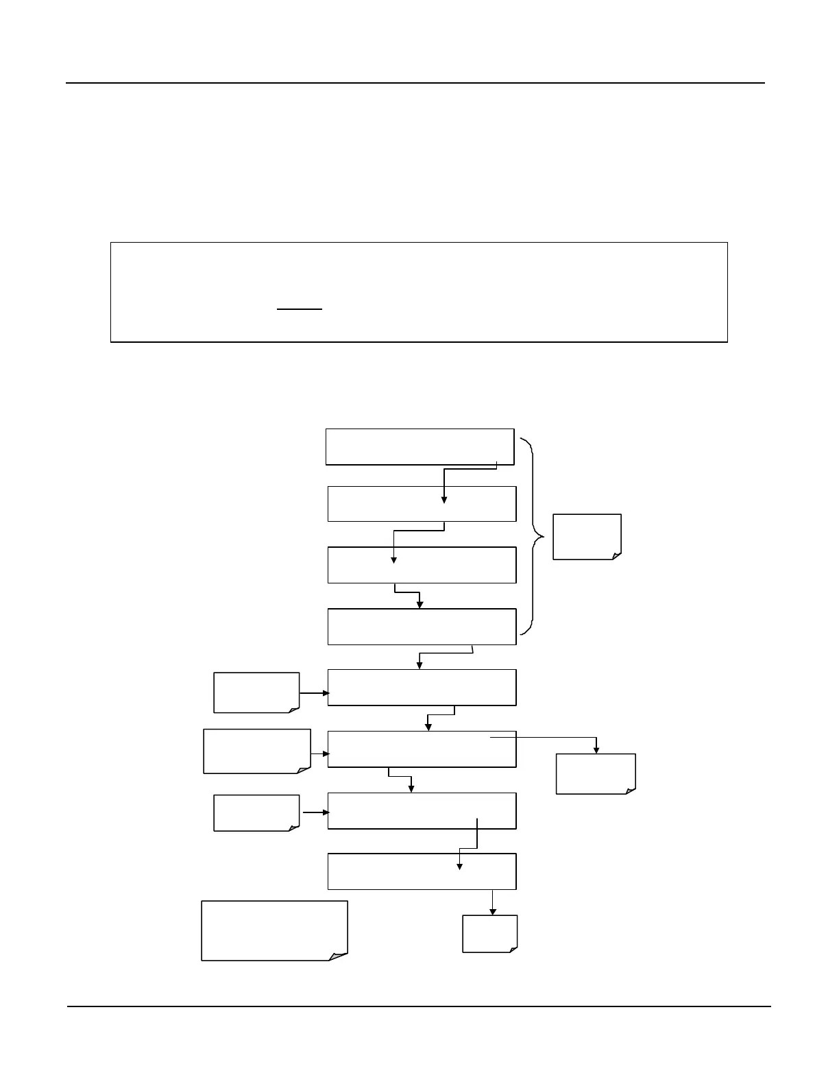
To enter the signal I/O test mode, press:
SAMPLE RANGE = 500.0 PPB O3 =XXX.X
< TST TST > CAL SETUP
EXAMPLE
SETUP X.X
CFG DAS RNGE PASS CLK MORE EXIT
SETUP X.X
COMM VARS DIAG HALT EXIT
DIAG SIGNAL I / O
PREV NEXT JUMP ENTR EXIT
DIAG I / O Test Signals Displayed Here
PREV NEXT JUMP PRNT EXIT
See Appendix A-
a complete list of
available SIGNALS
DIAG I / O JUMP TO: 5
0 5 ENTR
EXIT
To Jump
to Signal no 5:
SAMPLE_LED
DIAG I / O SAMPLE_LED = ON
PREV NEXT JUMP ON PRNT EXIT
Exit to Return
to the
Diag Menu
SETUP X.X ENTER DIAG PASS: 818
8 1 8 ENTR EXIT
keys to move UP or
DOWN one signal type.
Use the JUMP key go directly
to a specific Signal
(see Appendix A-4 for Jump
address numbers.
Pressing the PRNT Key will send a
formatted printout over the Serial I/O Port.
This Requires that one of the
RS-232/485 com ports be active and
connected to a peripheral device.
Press Exit to
return to the
SAMPLE Mode
display