Getting Started Model 400E Ozone Analyzer
Instruction Manual
26 P/N 04316 Rev: B
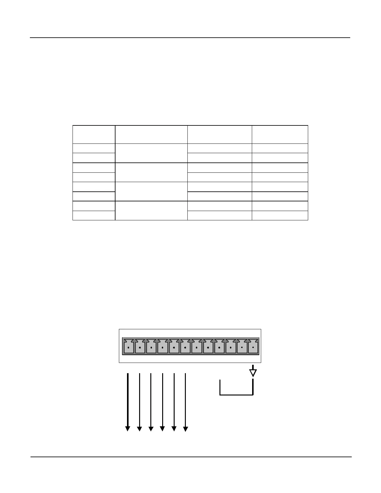
The output, labeled A4 is special. It can be set by the user (see Section 6.5.7)
to output any one of the parameters accessible through the <TST TST> keys
of the intruments Sample Display.
The standard configuration for these outputs is 0 – 5 VDC. An optional Current
Loop output is available for each. Pin-outs for the Analog Output connector at
the rear panel of the instrument are located in Table 3-1.
Table 3-1: Analog Output Pin Outs
Pin Analog Output
Standard
Voltage Output
Current
Loop Option
1 V Out I Out +
2
A1
Ground I Out -
3 V Out I Out +
4
A2
Ground I Out -
5 Not Available Not Available
6
A3
Not Available Not Available
7 V Out Not Available
8
A4
Ground Not Available
The default analog output voltage setting of the 400E O
3
Analyzer is 0 – 5 VDC
with a range of 0 – 500 ppb.
To change these settings, see Sections 6.4 and 6.5.
3. If you wish utilize the analyzer’s Status Outputs to interface with a device that
accepts logic-level digital inputs, such as Programmable Logic Controllers (PLC’s)
they are accessed via a 12 pin connector on the analyzer’s rear panel labeled
STATUS.
STATUS
1 2 3 4 5 6 7 8 D +
S
Y
S
T
E
O
K
H
I
G
R
A
N
G
E
C
O
N
V
A
L
I
D
Z
E
R
O
C
A
L
S
P
A
C
A
L
D
I
A
G
M
O
D
E


 To Next Page