Getting Started Model 400E Ozone Analyzer
Instruction Manual
30 P/N 04316 Rev: B
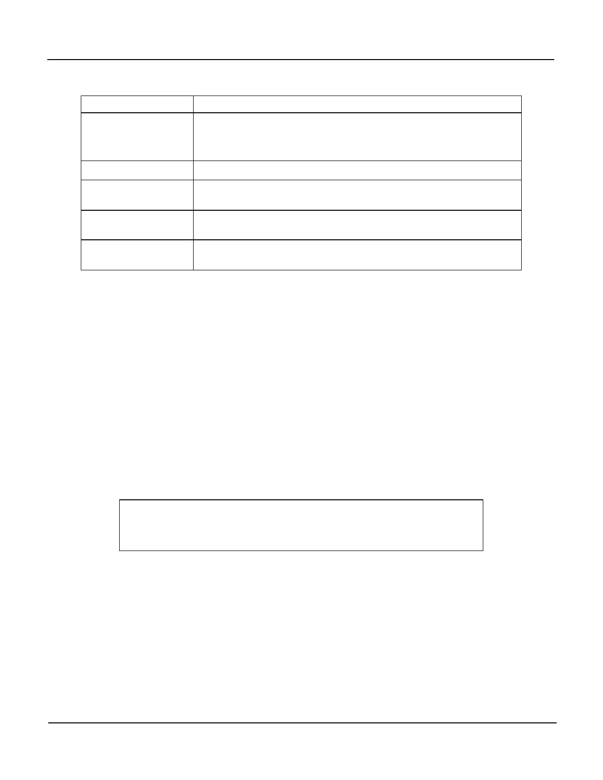
Table 3-2: Inlet Outlet Nomenclature
Rear Panel Label Function
Sample
Connect a gas line from the source of Sample Gas here.
Calibration gasses are also inlet here on instruments without
Zero/Span/Shutoff Valve Options installed.
Exhaust
Connect an exhaust gas line of not more than 10 meters long here.
Span
On Instruments with Zero/Span Valve Options installed, connect a gas
line to the source of Calibrated Span Gas here.
Zero Air
On Instruments with Zero/Span Valve Options installed, connect a gas
line to the source of Zero Air here.
Dry Air
On instruments with Internal Zero Air Options installed attach a gas
line to the source of Dry Air here (< -20°C dew point).
2. Attach a sample inlet line to the sample inlet port. Ideally, the pressure of the
sample gas should be at ambient pressure.
The SAMPLE input line should not be more than 2 meters long.
Figure 3-3 depicts the pneumatic flow for this analyzer in its basic
configuration.
Figure 3-4 depicts the pneumatic flow for this analyzer with the
Zero/Span/Valve Option installed.
Some applications, such as EPA monitoring, require multipoint calibration checks
where Span gas of several different concentrations is needed. We recommend using
a Gas Dilution Calibrator such as a T-API Model 700 with internal photometer
option.
NOTE
Maximum pressure of gas at the Sample Inlet should not
exceed 1.5 in-Hg above ambient.
 Loading...


