Model 400E Ozone Analyzer
Instruction Manual
Optional Hardware and Software
P/N 04316 Rev: B 49
5.3. Zero/Span Valves (Option 50)
The Model 400E Ozone Analyzer can be equipped with a Zero/Span Valve Option for
controlling the flow of calibration gases generated from sources external to the
instrument. This option consists of a set of two solenoid valves located inside the
analyzer that allow the user to switch the active source of gas flowing into the
instrument’s Optical Bench between the Sample inlet, the Span Gas inlet and the
Zero Air inlet.
The user can control these valves from the front panel keyboard either manually or
by activating the instruments AutoCal feature (See Section 7.6).
The valves may also be opened and closed remotely via the RS-232/485 Serial I/O
ports (see Section 6.9) or External Digital I/O Control Inputs (See Section 6.8.2).
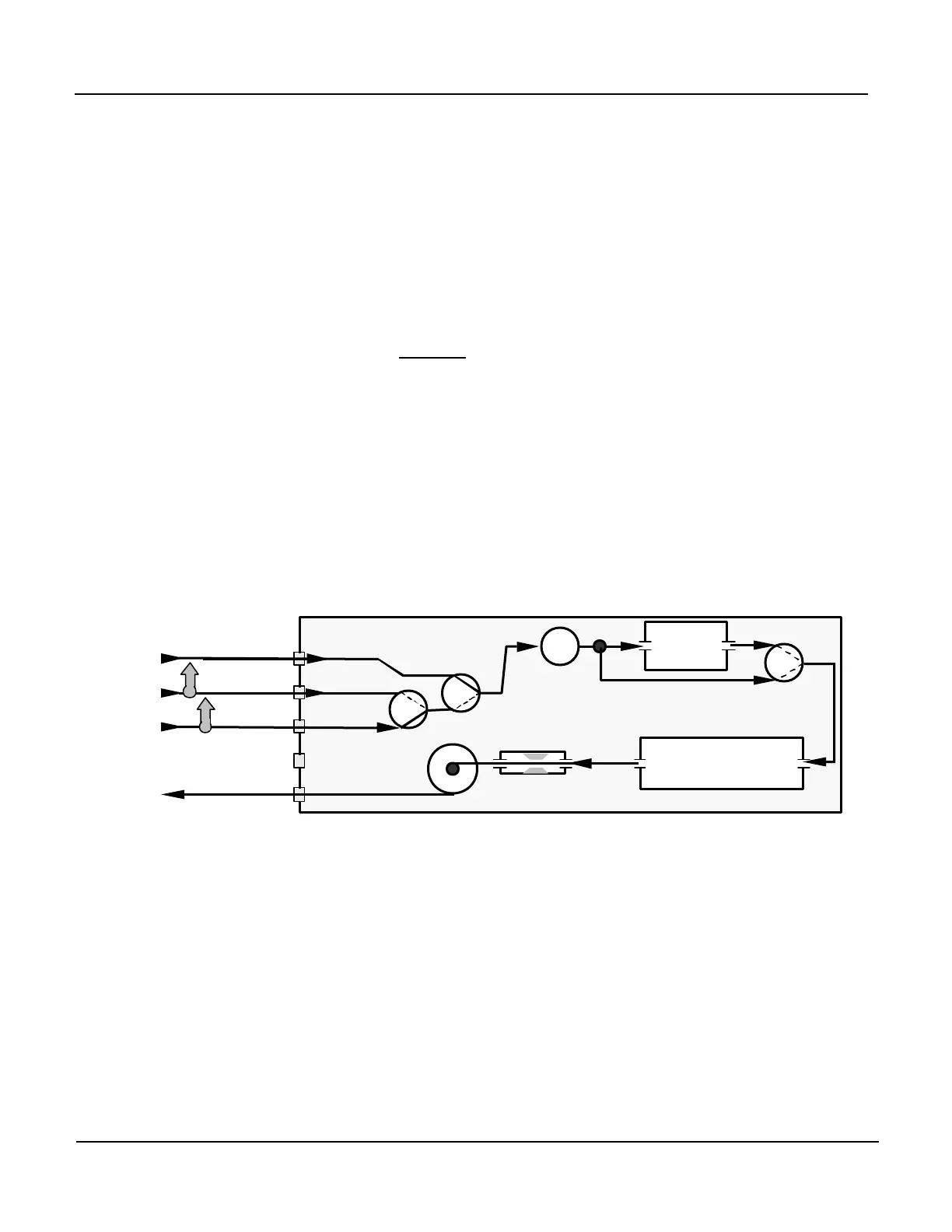
Figure 5-2 shows the internal pneumatic connections for a Model 400E Ozone
analyzer with the Zero/Span Valve Option installed.
Note that for the sake of clarity, the order in which the inlets/outlets appear may
not be the same order in which they are arranged on the rear panel of the
instrument.
Ozone
Scrubber
Optical
Bench
Option 50
Valve
Figure 5-2: Pneumatic Diagram – Zero/Span Valves
Span gas can by generated by a M700 Mass Flow Calibrator equipped with a
Photometer Option or an M401 UV Photometric Ozone Calibrator. Zero air can be
supplied by the API M701 Zero Air Module.
The instrument’s Zero Air and Span Gas flow rate required for this option is 800
cc/min. The US EPA recommends that the cal gas flow rate be at least 1600 cc/min.
Both supply lines should be vented outside the enclosure. In order to prevent back
diffusion and pressure effects, these vent lines should be not less than 2 meters in
length or greater than 10 meters in length.
 Loading...


