Model 400E Ozone Analyzer
Instruction Manual
Operating Instructions
P/N 04316 Rev: B 87
6.6.2.2. Manual Analog Output Calibration and Voltage
Adjustment
For highest accuracy, the voltages of the analog outputs can be manually
calibrated. Calibration is done through the instrument software with a voltmeter
connected across the output terminals (Figure 6-5). Adjustments are made using
the front panel keys by setting the zero-point first and then the span-point (Table
6-12).
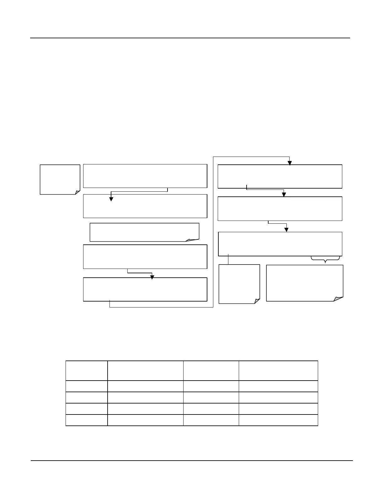
To select manual output calibration for a particular channel, activate the ANALOG
I/O CONFIGURATION MENU, then press:
DIAG AIO AOUT AUTO CAL: ON
ON ENTR EXIT
the main
sample display
DIAG ANALOG I / O CONFIGURATION
ENTR
DIAG AIO AOUTS CALIBRATED: NO
< SET SET> CAL EXIT
DIAG AIO CONC_OUT_2 RANGE: 5V
SET>
Toggles the
auto cal mode
ON/ OFF for
this analog
output channel
DIAG AIO CONC_OUT_2:5V, CAL
< SET SET> EDIT EXIT
Press
to select the analog outpu
be configured. Then press
EDIT
to continue
ENTR accepts the new setting
and returns to the previous menu.
EXIT
ignores the new setting and
returns to the previous menu.
DIAG AIO CONC_OUT_2 REC OFS: 0 mV
SET>
DIAG AIO CONC_OUT_2 AUTO CAL: ON
< SET SET> EDIT
Now the analog output channels should either be automatically calibrated or they
should be set to manual calibration, which is described next.
The software allows this adjustment to be made in 100, 10 or 1 count increments.
Table 6-12: Voltage Tolerances for Analog Output Calibration
FULL
SCALE
ZERO
TOLERANCE
SPAN
VOLTAGE
SPAN TOLERANCE
0.1 VDC ±0.0005V 90 mV ±0.001V
1 VDC ±0.001V 900 mV ±0.001V
5 VDC ±0.002V 4500 mV ±0.003V
10 VDC ±0.004V 4500 mV ±0.006V