Getting Started Model 400E Ozone Analyzer
Instruction Manual
24 P/N 04316 Rev: B
CAUTION
Never disconnect PCAs, wiring harnesses or electronic
subassemblies while the unit is under power.
4. Inspect the interior of the instrument to make sure all circuit boards and other
components are in good shape and properly seated.
5. Check the connectors of the various internal wiring harnesses and pneumatic
hoses to make sure they are firmly and properly seated.
6. Verify that all of the optional hardware ordered with the unit has been installed.
These are listed on the paperwork accompanying the analyzer.
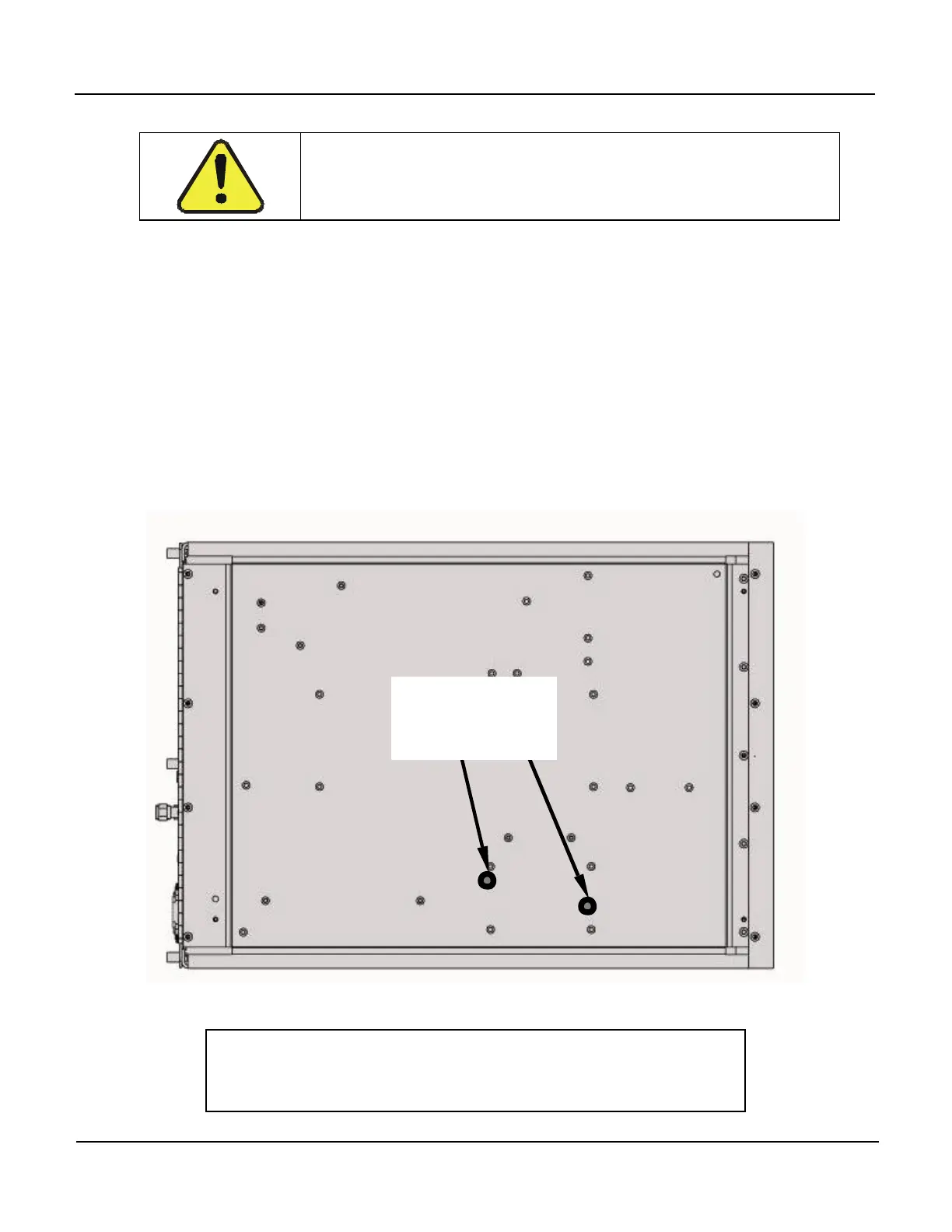
7. Once you have determined that no shipping damage exists, and the unit
includes all expected hardware options, remove all red colored shipping screws
from the bottom of the chassis as shown in Figure 3-1 below.
Shipping
Screws
Figure 3-1: Location of Shipping Screws, Chassis Bottom View
NOTE
Save these shipping screws and re-install them whenever
the unit is shipped to another location.


 To Next Page