Operating Instructions Model 400E Ozone Analyzer
Instruction Manual
72 P/N 04316 Rev: B
6.5. Analog Outputs – Range Configuration
The analyzer has four Analog Outputs accessible through a connector on the Rear
Panel.
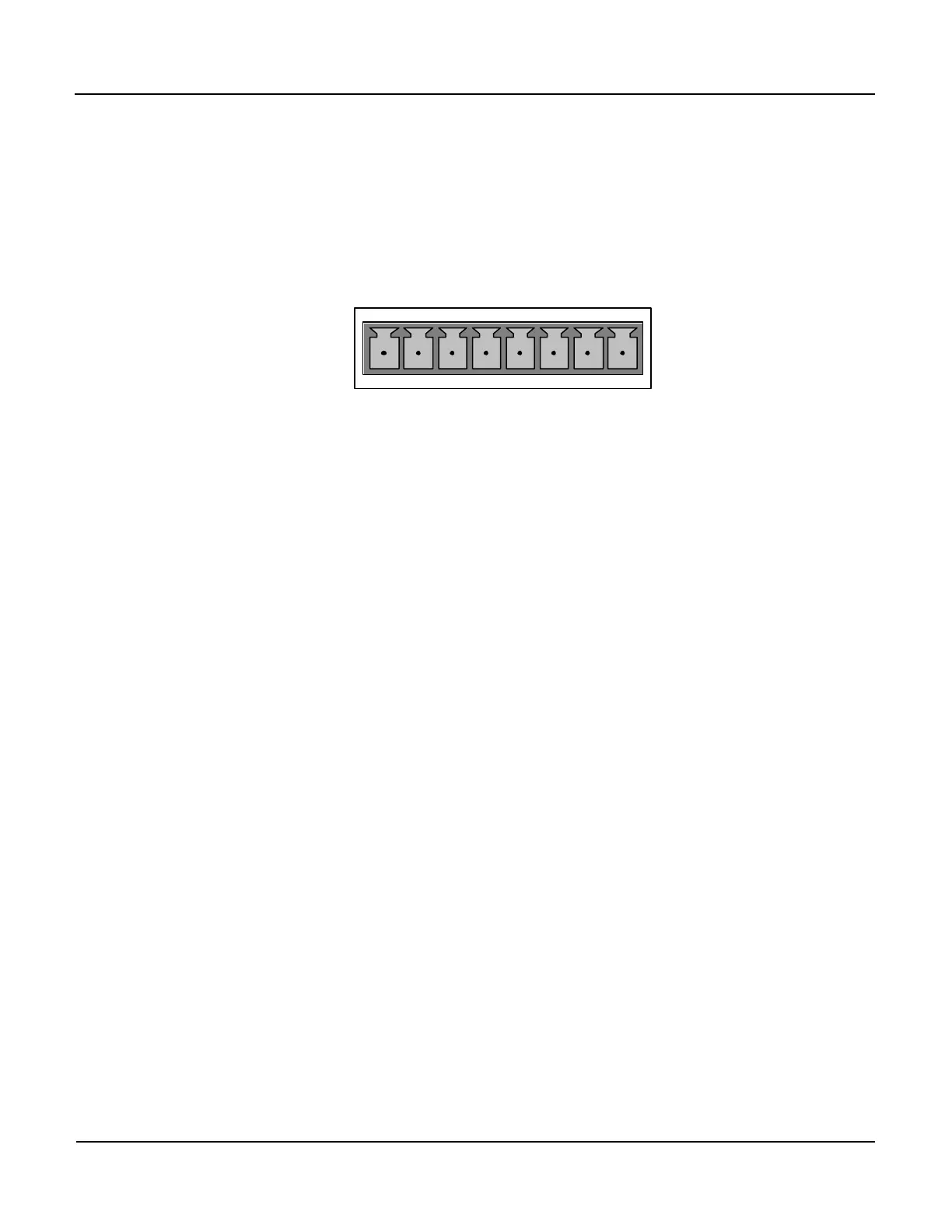
ANALOG OUT
A1 A2 A3 A4
+ - + - + - + -
All of these outputs can be configured either at the factory or by the user for full
scale outputs of 0.1 VDC, 1 VDC, 5 VDC or 10 VDC. Additionally A1 and A2 may be
equipped with optional 0-20 mADC current loop drivers and configured for any
current output within that range (e.g. 0-20, 2-20, 4-20, etc.).
The A1 and A2 channels output a signal that is proportional to the O
3
concentration
of the Sample Gas. These ranges can have the electronic output, the actual signal
level of the output voltage or current, scaled independently (see Section 6.6) to
match the input requirements of the recorder or datalogger.
They can also have their units of measure and measure span adjusted.
EXAMPLE:
A1 OUTPUT: Output Signal = 0-5 VDC representing 0-1000 ppb concentration
values.
A2 OUTPUT: Output Signal = 0 – 10 VDC representing 0-500 ppb
concentration values.
Additionally, these two outputs can be configured to operate independently or be
slaved together.
The output, labeled A4 is special. It can be set by the user to output any one of the
parameters accessible through the <TST TST> keys of the instruments Sample
Display. Range Scaling is dependent on the specific variable chosen (see Section
6.5.7).
Output A3 is not available on the Model 400E O
3
Analyzer.