Operating Instructions Model 400E Ozone Analyzer
Instruction Manual
84 P/N 04316 Rev: B
6.6.1. Analog Output Range Selection and Offset Adjustment
The final step in configuring the analyzer’s three analog output channels is to set
the electronic signal type and range of each channel. This consists of selecting a
type, voltage or current (if an optional current output driver has been installed),
and a signal level that matches the input requirements of the recording device
attached to the channel. A bipolar offset can be also added to the signal if
required.
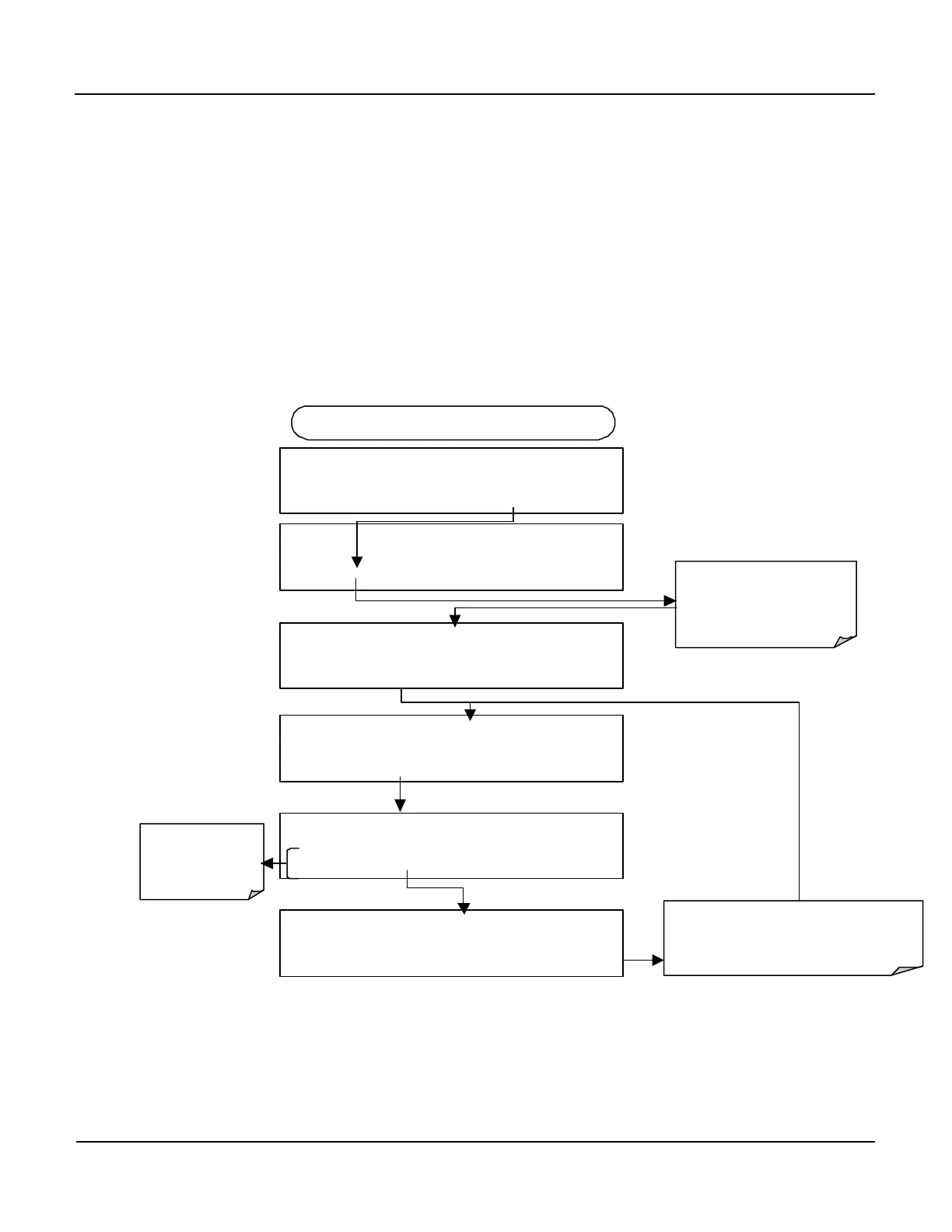
To select an output signal type (DC Voltage or current) and level for one output
channel, activate the ANALOG I/O CONFIGURATION MENU, then press:
DIAG AIO
SET> EDIT EXIT
DIAG ANALOG I / O CONFIGURATION
PREV NEXT ENTR EXIT
DIAG AIO AOUTS CALIBRATED: NO
< SET SET> CAL EXIT
FROM ANALOG I/O CONFIGURATION MENU
DIAG AIO OUTPUT RANGE: 5V
10V
These keys set
the signal level
and type of the
DIAG AIO CONC_OUT_2:5V, CAL
< SET SET> EDIT EXIT
Press SET> to select the
analog output channel to be
configured. Press
EDIT
to
continue
Pressing ENTR records the new setting
and returns to the previous menu.
Pressing EXIT
ignores the new setting and
returns to the previous menu.
DIAG AIO OUTPUT RANGE: 10V
10V
ENTR EXIT
 Loading...


