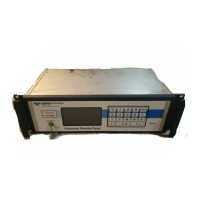
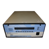
Model 400E Ozone Analyzer
Instruction Manual
Getting Started
P/N 04316 Rev: B 25
8. VENTILATION CLEARANCE: Whether the analyzer is set up on a bench or
installed into an instrument rack, be sure to leave sufficient ventilation
clearance.
Area
Minimum Required
Clearance
Back of the instrument 4 in.
Sides of the instrument 1 in.
Above and below the instrument 1 in.
Various rack mount kits are available for this analyzer. See Section 5.1 of this
manual for more information.
3.1.1. Electrical Connections
CAUTION
Check the voltage and frequency label on the rear panel of the
instrument (See Figure 3-2) for compatibility with the local
power before plugging the M400E into line power.
CAUTION
Power connection MUST have functioning ground connection.
1. Refer to Figure 3-2 for the location of the rear panel electrical connections.
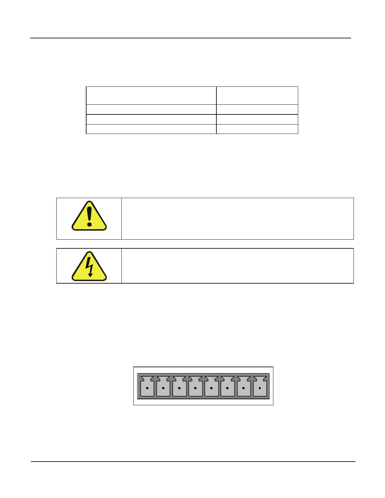
2. Attach a strip chart recorder and/or data-logger to the appropriate contacts of
the Analog Out connecter on the rear panel of the analyzer.
ANALOG OUT
+ - + - + - + -
The A1 and A2 channels output a signal that is proportional to the O
3
concentration
of the Sample Gas.


 To Next Page