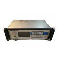
Getting Started Model 400E Ozone Analyzer
Instruction Manual
28 P/N 04316 Rev: B
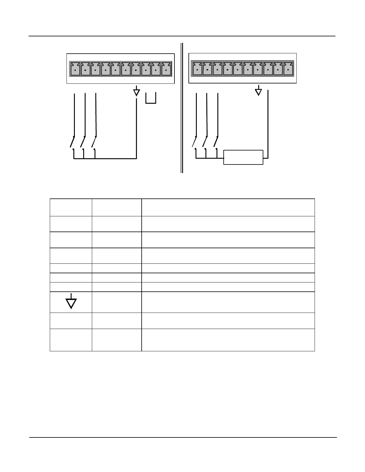
CONTROL IN
A B C D E F U +
O
S
P
A
N
E
R
O
P
A
N
CONTROL IN
A B C D E F U
+
L
O
S
P
A
N
Z
E
R
O
S
P
A
N
+
Supply
Local Power Connections
External Power Connections
Input #
Status
Definition
ON Condition
A
REMOTE ZERO
CAL
The Analyzer is placed in Zero Calibration mode. The mode
field of the display will read ZERO CAL R.
B
REMOTE
LO SPAN CAL
The Analyzer is placed in Lo Span Calibration mode. The
mode field of the display will read LO CAL R.
C
REMOTE
SPAN CAL
The Analyzer is placed in Span Calibration mode. The mode
field of the display will read SPAN CAL R.
D SPARE
E SPARE
F SPARE
Digital Ground
The ground level from the analyzer’s internal DC Power
Supplies (same as chassis grount).
U
External Power
input
Input pin for +5 VDC required to activate pins A – F.
+ 5 VDC output
The internaly generated 5VDC power supply is available on
this pin. To activate inputs A – F place a jumper between this
pin and the “U” pin.
5. If you wish to utilize either of the analyzer’s two serial interfaces, refer to
Section 6.9 of this manual for instructions on their configuration and usage.


 To Next Page