APPENDIX A-4: M400E Signal I/O Definitions, Revision .2 Model 400E Instruction Manual
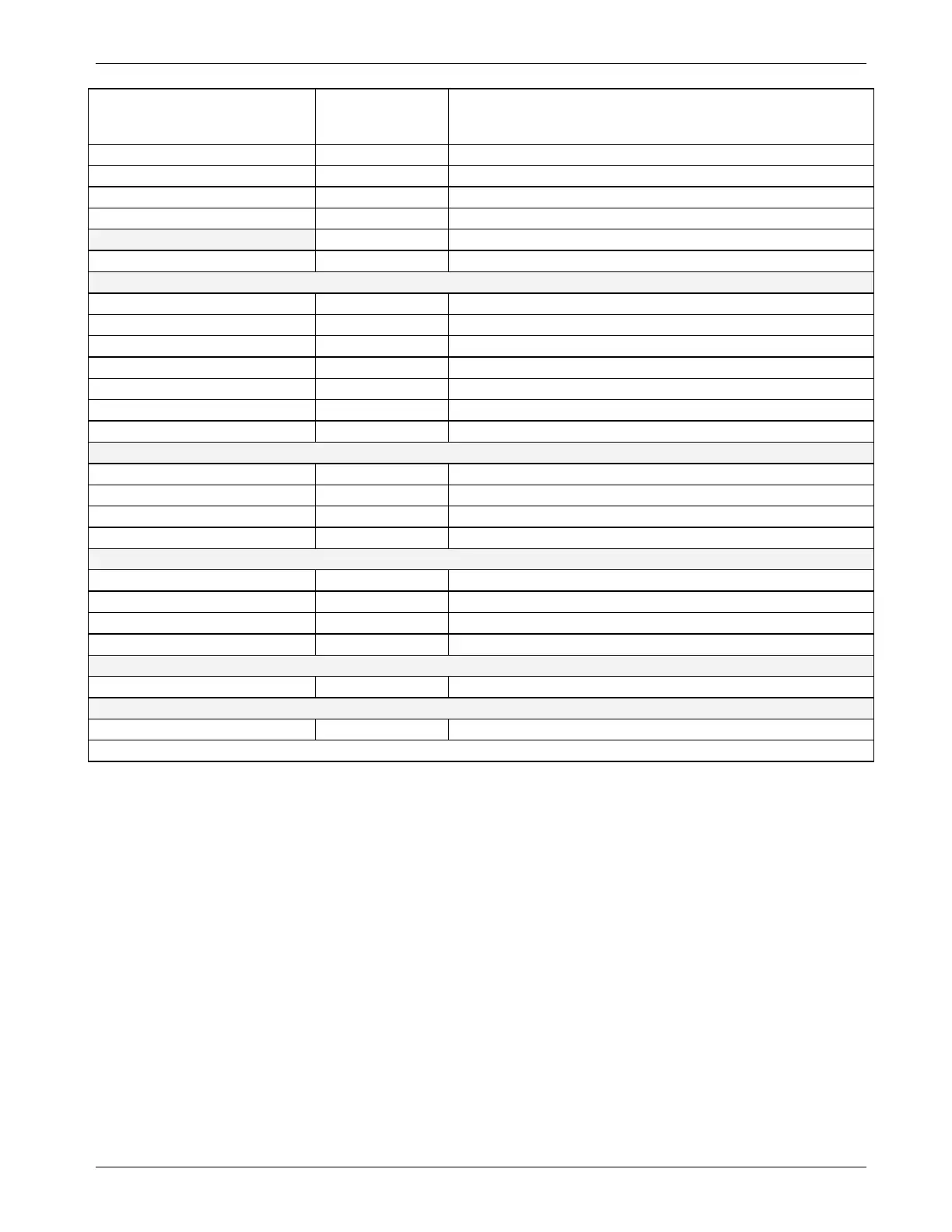
SIGNAL NAME BIT OR
CHANNEL
NUMBER
DESCRIPTION
REF_4096_MV 9 4.096V reference from MAX6241
10–11 Spare
O3_SCRUB_TEMP 12 O
3
scrubber temperature
13 Spare
14 DAC loopback MUX
REF_GND 15 Ground reference
Rear board temperature MUX analog inputs
BOX_TEMP 0 Internal box temperature
SAMPLE_TEMP 1 Sample temperature
PHOTO_LAMP_TEMP 2 Photometer lamp temperature
O3_GEN_TEMP 3 O
3
generator lamp temperature
4–5 Spare
TEMP_INPUT_6 6 Diagnostic temperature input
TEMP_INPUT_7 7 Diagnostic temperature input
Rear board DAC MUX analog inputs
DAC_CHAN_0 0 DAC channel 0 loopback
DAC_CHAN_1 1 DAC channel 1 loopback
DAC_CHAN_2 2 DAC channel 2 loopback
DAC_CHAN_3 3 DAC channel 3 loopback
Rear board analog outputs
CONC_OUT_1 0 Concentration output #1
CONC_OUT_2 1 Concentration output #2
2 Spare
TEST_OUTPUT 3 Test measurement output
I
2
C analog output (AD5321), default I
2
C address 18 hex
PHOTO_LAMP_DRIVE 0 O
3
photometer lamp drive (0–5V)
I
2
C analog output (AD5321), default I
2
C address 1A hex
O3_GEN_DRIVE 0 O
3
generator lamp drive (0–5V)
1
Internal span option.
18 04402 Rev C.3


 To Next Page