Section 2 – SR-2 Hardware Description
5
L3
3
L2
1
L1
4
T2
2
T1
6
T3
98 97 9596
NO NC
MCBMCA
OVL
HC
THERMO KING
9131C98G06
L1
L2
L3
0202
PSM
L1
L2 L3
T1 T2
T3
L1
L2 L3
T1 T2
T3
1
L1
3
L2
5
L3
13
NO
2
T1
4
T2
6
T3
14
NC
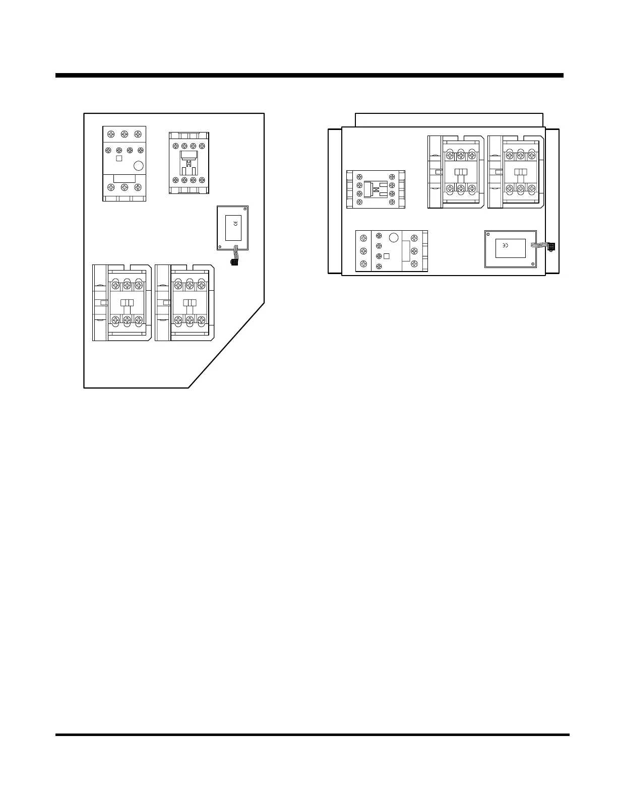
SB Unit Electric Standby Components
These components are located in separate control
box on compressor side of the unit.
5
L3
3
L2
1
L1
4
T2
2
T1
6
T3
98 97 9596
NO NC
MCB
MCA
OVL
HC
PSM
THERMO KING
9131C98G06
L1
L2
L3
0202
L1
L2 L3
T1 T2
T3
L1
L2 L3
T1 T2
T3
1
L1
3
L2
5
L3
13
NO
2
T1
4
T2
6
T3
14
NC
SL Unit Electric Standby Components
These components are located in the unit control
box.
2-31
31 January 2005
 Loading...