120
25. ROUTE SURVEYING
4. Input the coordinates of the IP point, then press [OK].
• The azimuth angle to the IP point can be set by pressing
[AZMTH] on the second page. Press [COORD] to return to
coordinate input.
5. Input the reference point follow-up distance in "St. ofs".
Input the target point follow-up distance in "Sta..ing".
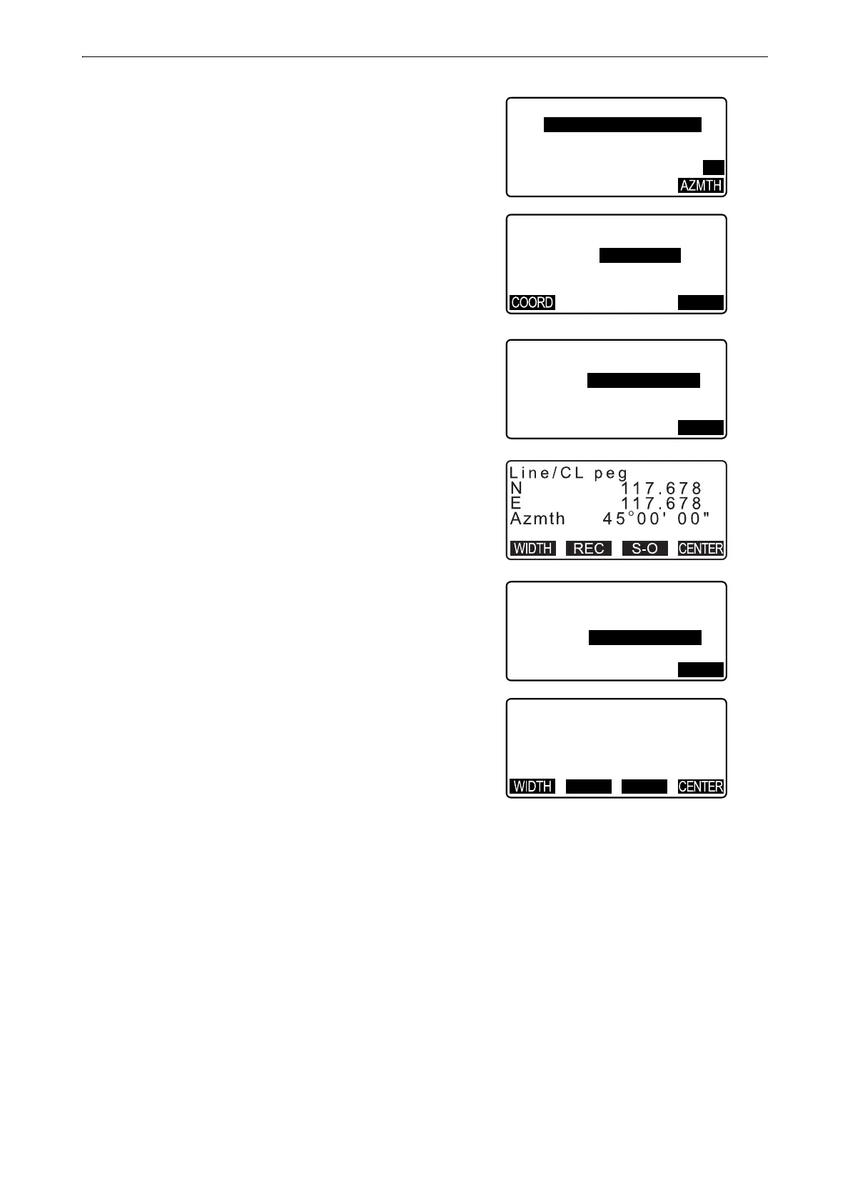
6. Press [OK] in the screen shown in step 5 to calculate the
center peg coordinates. The coordinates and azimuth angle
are then displayed on the screen.
7. Press {ESC} twice to finish Straight Line calculation and
return to <Road>.
• Press [WIDTH] to move to the width peg setting screen.
The coordinates of the width peg can be found by inputting
the route width and pressing [OK].
• The center peg can be stored as a known point in the
current job by pressing [REC].
"30.1 Registering/Deleting Known Point Data"
• The center peg can be set-out by pressing [S-O].
"15. SETTING-OUT MEASUREMENT"
• Press [CENTER] to return to the center peg setting screen.
• When the azimuth angle is set after the coordinates have been input in step 4, if the coordinates are deleted
the azimuth angle is given priority.
• Offset/Follow-up distance input range: 0.000 to 99999.999 (m)
• Route width input range: -999.999 to 999.999 (m)
N p :
E p :
2 0 0 . 0 0 0
L i n e / I P
2 0 0 . 0 0 0
P2
L i n e / I P
A z m t h
4 5 . 0 0 0 5
OK
L i n e / C L p e g
!S t . o f s
!S t a . . i n g
0 . 0 0 0 m
2 5 . 0 0 0 m
OK
L i n e / W i d t h P e g
C L o f s
S t a . . i n g
5 . 0 0 0 m
2 5 . 0 0 0 m
OK
N
E
1 1 4 . 1 4 2
L i n e / W i d t h P e g
1 2 1 . 2 1 3
REC S-O
 Loading...